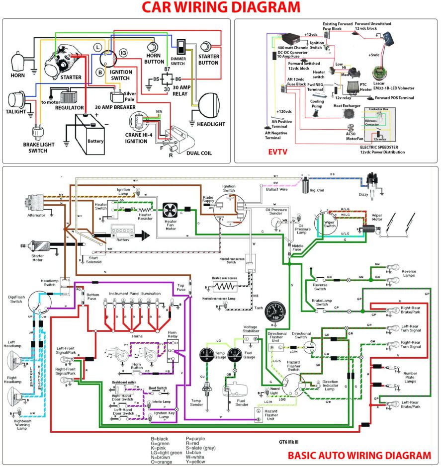
Automotive Wiring Diagrams in Australia: How to Read an Electrical Circuit
The use of automotive wiring diagrams Australia is essential for anyone who wants to successfully and safely install, maintain, or disconnect electrical components. Wiring diagrams provide users with the information they need to quickly understand the layout and connections of electrical appliances and devices. To read a particular wiring diagram, it is important to first identify the symbols used, as well as the component's purpose.
Sketching out wiring diagrams by hand can be difficult, which is why a comprehensive knowledge of the diagram format is important for any project or installation. Therefore, understanding how the diagrams are laid out and what components are listed on them, as well as their proper operation and function, is the key to accurately reproducing them. With this in mind, this article looks to provide a guide to automotive wiring diagrams in Australia and how individuals can use them effectively.
Understanding Wiring Diagrams
A wiring diagram is a mathematical representation of every element in an electrical system. It shows how electrical power is transmitted through the circuit, where the wires go, and what components are connected to each other. Wiring diagrams are usually drafted in either CAD or paper-based formats, allowing users to quickly understand the wiring sequence. In addition, each component will be labeled, allowing users to identify the correct wiring connections easily.
Interpreting the Symbols
Reading a wiring diagram correctly means understanding each of the symbols used. Each symbol has its own unique representation, meaning the diagram can be read almost like a text, if the user is familiar with all the symbols. The most commonly encountered symbols in automotive wiring diagrams include lines, arrows, coils and other shapes. Additionally, some diagrams may include a terminal, fuse or connector, while others may indicate a switch, relay, or battery.
Color Codes
Another important aspect of interpreting wiring diagrams is to understand the color codes employed. While some diagrams may only use black and white, others may also use a range of different colors to signify the resistance of a particular connection. For example, white indicates low current-carrying capacity and black indicates high current-carrying capacity. In addition, other colors may be used, such as red for power supply, yellow for ground, and orange for data or telephone lines.
What is the Purpose of an Automotive Wiring Diagram?
The purpose of an automotive wiring diagram is to provide an accurate and easy-to-understand visual illustration of the physical connections and components in an electrical system. This allows the user to save time and money when installing a system and reduces potential errors. For instance, in a car’s electrical system, the diagram helps depict each part’s function so that everyone involved can clearly see the possible faults that may arise and how they can be averted.
In conclusion, automotive wiring diagrams Australia can be a valuable resource for anyone looking to quickly understand the structure of an electrical system. By understanding the symbols and color codes used in these diagrams, as well as the purpose of automotive wiring diagrams, users can easily interpret the plans and make educated decisions during the installation, maintenance, or disconnection of components.

Car Wiring Diagram Construction

Diagnosing Voltage Drops Electrical Automotive Troubleshooting Fluke

Can Bus Wiring Diagram A Basics Tutorial Tek Eye

Honda Car Pdf Manual Wiring Diagram Fault Codes Dtc

Trailer Wiring Diagram Sea Doo Forum

Trailer Wiring Diagram Lights Brakes Routing Wires Connectors

How To Read Car Wiring Diagrams For Beginners Emanualonline Blog

92 F250 7 Pin Trailer Wiring At Rear Ford Truck Enthusiasts Forums

12v Solar Panel Wiring Diagrams For Rvs Campers Van S Caravans

Trailer Wiring Diagrams Exploroz Articles

Electrical Wiring Color Codes Important

3 Types Of Vehicle Wiring Diagrams For Towing

Rellim Wiring Diagrams Vol 7 Haynes Manuals

Australian Trailer Plug And Socket Pinout Wiring 7 Pin Flat Round Connector Find Thingy

1973 1979 Ford Truck Wiring Diagrams Schematics Fordification Net

How To Read Automobile Wiring Diagrams

Porsche Car Pdf Manual Wiring Diagram Fault Codes Dtc

Diy Solar Wiring Diagrams For Campers Vans Rvs Explorist Life