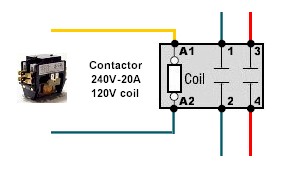
Getting to Know Contactor Wiring Diagrams
Understanding the fundamentals of contactors and the associated wiring diagrams is essential for controlling power in many machines and products. While it might sound complicated, the basics of contactor wiring are easy to comprehend.
Contactor wiring diagram technology can provide a simple way to control complex operations consisting of multiple motor and light controls. In addition, when utilizing contactors or relays with other components, like switches and lights, contactor wiring diagrams provide a comprehensive picture of how these functions interact.
What is a Contactor Electrical Device?
A contactor is a piece of electrical equipment that allows current to be switched on and off to power an electrical device. It contains two separate contacts; an open contact that closes when a set amount of electricity is present, allowing the current to flow and enable the device to power up. A second contact then closes, which causes the current to continue flowing and keep the device powered.
Contactor wiring diagram represents how the contactor is wired with the other components in the circuit. This includes wires such as power, neutral, and ground, as well as switches and lights, indicating how the contactor acts upon each element and providing information on how each component should be wired in order to function correctly.
How to Use Contactor Wiring Diagrams
Contactor wiring diagrams are designed to show how different elements are connected and to illustrate how a complex array of relays and switches interact with each other. The diagram breaks up the circuit into individual components, usually represented by symbols and colours.
Wires and other components are shown using wire colours, making it easier to identify the elements connected and their position in the circuit. Additionally, each component symbol is colour-coded, so you can better visualize which elements are participating in a certain operation at any particular time.
Understanding contactor wiring diagrams also helps users to decide how they want to connect to one another. For instance, changing the polarity of a switch could reverse the functionality of an output — something that would not be immediately obvious when looking at the circuit.
Benefits of Using Contactor Wiring Diagrams
Using contactor wiring diagrams has several advantages over traditional methods of circuit wiring. Most significantly, it reduces the complexity of the circuit, making troubleshooting much easier. It also improves the speed of installation and helps eliminate confusion when connecting multiple devices. Furthermore, wiring diagrams come with detailed instructions for proper usage.
Another advantage is flexibility. Contactor wiring diagrams can easily be adjusted as needed to accommodate changes in the circuit or a modified design. This makes it easier to work with existing circuits without having to rewire them from scratch.
Safety Considerations?
When working with contactors or wiring diagrams, there are numerous safety considerations to keep in mind. Both contactors and wiring diagrams must comply with local standards and regulations, including those related to electricity and systems deployment. In addition to this, operators must follow the manufacturer’s instruction carefully and make sure the wiring connections are properly secured to prevent any potential electrical shock.
Additionally, tools and materials used should be appropriate and rated to handle the specific voltage of the project. Proper protective equipment, such as eyewear and gloves, must also be worn to protect against electrical shock and other hazards.
Conclusion
Contactor wiring diagrams provide a convenient and intuitive way to control complex operations. As long as you understand the basics and take the necessary safety precautions, you can use them to improve efficiency and reduce wiring times. With the right knowledge and approach, contactor wiring diagrams can help make any electrical project a success.

How To Wire A Contactor 8 Steps With Pictures Wikihow
How Do I Connect A Contactor And Overload To Create Direct On Line Dol Starter Schneider Electric Ireland

Contactor Pole Wiring Question Homebrew Talk Beer Wine Mead Cider Brewing Discussion Forum

Magnetic Contactor Working Principle Construction Fundamentals

Main And Auxiliary Circuit Diagrams Of Switching Three Phase Motors Via Contactor Directly Eep

3 Phase Motor Contactor Wiring Diagram Guide Springer Controls

Wiring Diagram Contactor Electrical Wires Cable Switches Circuit Breaker Others Electronics Png Pngwing

Overload Relay Connection Diagram Types And Applications

220v Ac Contactor Wiring Method And Physical Diagram
25a Power Contactors Silent With Handle
Wiring Schematic Diy Electric Car Forums

I Have A Master Electrician Working On My House But He Has Never Installed Mechanically Held Square D 8903 Lx
Contactor Wiring Diy Home Improvement Forum
Contactor Diagram Electronics Forum Circuits Projecticrocontrollers

Using Star Delta Motor Control With Circuit Diagrams Turbofuture

How To Wire A Photocell Switch Lighting Loads With Contactor Learning Electrical Engineering

How To Wire A Contactor 8 Steps With Pictures Wikihow
Square D Wiring Diagrams For Contactors Starters Relays And Controllers Catalog Catalogue Schneider Electric