Guide to Understanding Electric Motor Wiring Diagrams
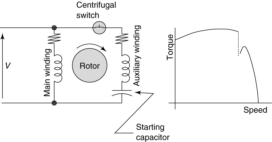
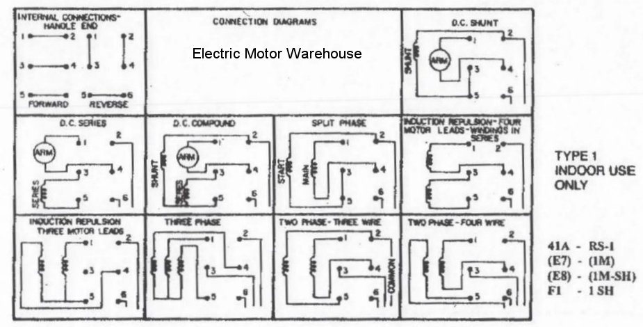
Electrical wiring is an essential component of electrical repairs and maintenance. Many homeowners and professionals begin their projects with poor understanding of the major components and details of a wiring system. This can lead to costly mistakes and delays in getting the job done. Through a comprehensive understanding of the electrical wiring diagrams, individuals can save time and money while performing electrical repairs and installations. In this article, we will explicitly focus on understanding single phase electric motor wiring diagrams and the differences between them.
Overview and Master Wiring Diagrams
Before anything else, it is important to understand what a wiring diagram actually is and how it works. A wiring diagram is a visual representation of an electric circuit’s wiring and components. It shows what kinds of wires go where and how they are connected. They also provide information about special features and features that one needs to be aware of when installing or servicing the device. Every wiring diagram should include a master diagram, which describes the overall structure of the circuit.
How to Read Single Phase Electric Motor Diagrams
Now that we have discussed the basics of wiring diagrams, let us move onto single phase electric motor diagrams. The first thing to do when attempting to read a motor diagram is to understand the symbols used. Motor diagrams often use symbols to represent different switch types, resistors, capacitors, fans, motors and other components. Additionally, it may also have marks to denote specialized wires, terminals, and other connectors. After understanding the symbols, one can then identify motor output connections and motor start/stop signals.
Power Supply Connections
When it comes to power supply connections, three-phase systems require three lines for each voltage source. A single-phase system only requires two wires for each voltage source. This is why single-phase systems are generally easier to install and wire for compared to three-phase systems. In the case of a single-phase electric motor, the power source will typically be a main line from the house panelboard or a small generator. Additionally, some motors are specified with a dual voltage rating – in this case two inputs from the same power source are required.
Control Circuits
Control circuits can be complicated, so it is important to make sure that all connections are correct. For a single-phase motor, the power supply connections should go to the ‘run’ side of the control switch, while the control circuits should be wired to the ‘start’ side. In some cases, there may also be special features such as reversing or overload protection. When these features are present, it is important to follow the manufacturer’s instructions closely.
Comprehensive Knowledge
Understanding wiring diagrams has become much simpler over time, largely due to more modern software giving engineers the ability to effectively map out a circuit diagram in great detail. Some older diagrams may be less than intuitive to interpret, but a good understanding of the components and concepts should enable you to decipher them. With such a wide range of components, wiring diagrams can look intimidating at first glance, but a comprehensive knowledge should simplify the process and make electric motor wiring diagrams easier to interpret and understand.
Oriental Electrical Services Ltd D O L Single Phase Motor Wiring Diagram Try This Facebook

Wiring Diagram Electric Motor Single Phase Power Baldor Company Three Braking Angle White Text Png Pngwing

Motor Wiring Diagrams Groschopp

Single Phase Cap Start Run Motors Rotor Uk

Aim Manual Page 57 Single Phase Motors And Controls Motor Maintenance North America Water Franklin Electric

Single Phase Induction Motors Electric Motor
How Can We Switch A Single Phase Motor Forward Reverse And On Off With 6 Pin Quora

Aim Manual Page 57 Single Phase Motors And Controls Motor Maintenance North America Water Franklin Electric

Aim Manual Page 55 Single Phase Motors And Controls Motor Maintenance North America Water Franklin Electric
Single Phase Motor Connection Diagram And Wiring Procedure Etechnog
.png?strip=all)
Acp M Ac Induction Motors

Wiring A 3 Hp Electric Motor Doityourself Com Community Forums

Types Of Single Phase Induction Motors Motor Wiring Diagram Electrical Academia

How To Wire A Single Phase 230v Motor Hunker

Rs 1 Sh Relay Controls 5 Hp 2 Electric Motor Reversing Drum Switch Position Maintained

Fig 6 Split Phase Motor Wiring Diagram Electrical A2z
What Is The Wiring Of A Single Phase Motor Quora

Need Help Wiring 1hp Motor To A Drum Switch In General Board

3 Ways To Troubleshoot Ac Motors With A Circuit Tester

