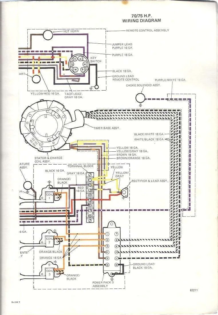
Understanding Evinrude Outboard Ignition Switch Wiring Diagrams
Outboard motors have been used in boating to provide a reliable power source for many years. When it comes time to replace or repair your Evinrude outboard motor, understanding the wiring diagram is essential for a successful job. Knowing how to properly read wiring diagrams is essential for the safe and reliable operation of any outboard system.
The wiring diagram for an Evinrude outboard motor is divided into two main categories: ignition switches and other electrical components. Ignition switches are designed to control the flow of electricity from the starter circuit to the other components of the outboard such as the power trim, throttle controls, and other circuits. Other components such as rectifiers and relays also rely on the wiring diagram to provide power and ensure proper operation. In this article, we’ll further examine exactly how each component functions in the context of the Evinrude outboard motor wiring diagram.
The Starter Relay in the Evinrude Wiring Diagram
The starter relay is the component responsible for safely transferring electrical power from the starter battery to the starter motor. The starter relay contains an internal chemical switch that responds to signals from the on/off switch. The starter relay is connected to the main power feed and connects to the starter motor when the on/off switch is activated. When the relay senses the signal, it will quickly enable the starter motor to begin spinning the flywheel.
The Power Trim and Tilt Control in the Evinrude Outboard Wiring Diagram
The power trim and tilt control provides the means for changing the depth and angle of the boat within a specific range. This system is typically composed of two separate circuits: the power trim trim circuit and the power tilt control circuit. The power trim trim circuit senses an increase in speed or load and adjusts the outdrive as necessary to accommodate for the change. The power tilt control circuit moves the outdrive using a solenoid that is triggered by a manual switch or a dash-mounted joystick.
The Throttle Control in the Evinrude Outboard Wiring Diagram
The throttle control circuit is responsible for controlling the speed of the outboard. The throttle control circuit is composed of two main components: the throttle cable and the throttle control switch. The throttle cable connects the switch to the carburetor or fuel injection system, whereas the switch allows you to adjust the speed of the outboard motor by modulating the flow of air and fuel through the intake. The power of the motor is determined by the opening and closing of the throttle valve, which is regulated by the throttle control switch.
The Alternator Charge Circuit in the Evinrude Outboard Wiring Diagram
The alternator charge circuit is critical for keeping the electrical system running smoothly. The alternator charges the battery and also provides direct voltage to the starter motor and various other electrical components. The alternator consists of several parts including the stator, regulator, brushes, and diode board. The alternator circuit in the wiring diagram is composed of three main components: the voltage regulator, the alternator impeller, and the alternator field coils.
The Rectifier and Regulator in the Evinrude Outboard Wiring Diagram
The rectifier and regulator are responsible for converting alternating current into direct current. The rectifier converts the AC current into DC current, whereas the regulator maintains a consistent voltage output regardless of changes in demand. The regulator is also responsible for regulating the amount of power that is supplied to the starter motor and other vital electrical components. Both the rectifier and regulator are crucial components in any outboard wiring system.
Conclusion
Understanding and correctly interpreting the Evinrude outboard motor wiring diagram is essential for the safe and reliable operation of any outboard system. It is important to pay close attention to all the components, connections, and diagrams associated with the wiring diagrams. By doing so, you can ensure that everything works as it should and provide the safety and dependability expected from an Evinrude outboard motor.

Free Outboard Wiring Diagrams Manuals Net

98 Johnson 150 Ficth Model J150ilecr Ignition Switch Wiring Question
1958 Evinrude Lark 35hp Ignition Wiring
Wimea Kabelloser Sicherheits Schalter At Www Svb De
Fiberglassics Tach Signal Wire 64 Lark Vi Forums
Gsx Fuelino Para Salvar Ou Dar Um Up No Alternador Retificador Regulador Diy Com Peças De Chevette Monza Facebook

Seachoice 11651 Johnson Evinrude Ignition Starter Switch Com

How To Wire A Johnson Ignition Switch

Evinrude Johnson Outboard Wiring Diagrams Mastertech Marine

Free Outboard Wiring Diagrams Manuals Net

Evinrude Johnson Service Manuals Spare Parts Catalog

Outboard Motor Ignition Switch F5h268 F5h078 9100 9830 9760 5005801 Mp41000 Mp41070 2 Mp52000 Mp51020 Mp51030 Mp51040 Mp51050 Outboardignition Com

Can You Please Provide An Electrical Circuit Diagram For Evinrude Ficht 115 Model Number E115fpxeec With Particular

Maintaining Johnson Evinrude 9

Continuouswave Whaler Reference Ignition Switch

Evinrude Johnson Outboard Wiring Diagrams Mastertech Marine
![]()
Icon Touch 4 3 Powering Off Barnacle Bill S Marine Supply
