Everything You Need to Know About Home Alarm Wiring Diagrams
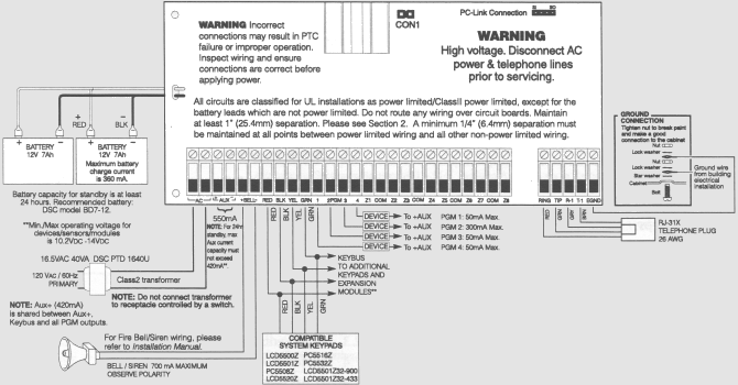
Wireless alarm systems are becoming increasingly popular with homeowners and professionals. Advanced security systems allow for complete customization of components based on individual needs. With the right tools and detailed wiring diagrams, it's easy to get started when installing a security system. Here, we'll look at home alarm wiring diagrams and why they're important.
Home alarm wiring diagrams provide an outline for your alarm system to help you get started. These diagrams are a valuable resource for installers and can be used to identify components or troubleshoot errors in the system. No matter what alarm system you choose, understanding the basics of a home alarm wiring diagram ensures you get the best performance out of your security system.
The Basic Components of Home Alarm Wiring Diagrams
Home alarm wiring diagrams will usually include the following basic components: the power source, ground conductor, signal line (for sensors and keypads), and output lines. The power source is usually a central power supply. The ground conductor provides continuity between components to avoid static electricity and interference. Last, each component must be connected to the correct line, typically color-coded for quick identification.
Types of Sensors Used in Home Alarm Wiring Diagrams
When setting up a home alarm system, there are several types of sensors used in wiring diagrams. A motion sensor will detect the movement of objects in its vicinity. Other types of sensors include door/window contacts which detect when a door or window is opened, smoke detectors which alert users to fire danger, and glass break sensors which detect when a window is broken. A photoelectric beam system uses a light beam that is broken by movement to trigger alarms.
How to Read a Home Alarm Wiring Diagram
In order to correctly install your home alarm system, a wiring diagram is essential. Here are some of the most common symbols used in home alarm wiring diagrams:
- Arrow - Indicates the direction of current flow.
- Circle - Represents a connection point.
- Line - Represents a wire.
- Triangle - Represents a switch.
- X - Represents a terminal.
- Plus Sign - Represents a positive power source.
- Minus Sign - Represents a negative power source.
- Letter - Represents a component or device.
- Number - Represents voltages measurements and connections.
You should also pay careful attention to colors and labels on the wiring diagram. Color-coding makes it easier to differentiate between components, and labels explain the function of each component.
Conclusion
Home alarm wiring diagrams are an invaluable tool when it comes to installing a secure and efficient security system. Knowing how to read a wiring diagram is the key to understanding and troubleshooting your alarm system. With the right wiring diagram and a little patience, it’s easy to set up the system you need for complete home protection.

Car Alarm Circuit Page 2 Automotive Circuits Next Gr
What Is Addressable Fire Alarm System Wiring Diagram Etechnog

How To Make Burglar Alarm Using Arduino Uno

Modular Burglar Alarm Under Repository Circuits 36025 Next Gr

Example Dsc Security System Burglar Alarm

China Addressable Burglar Home Smart Fire Alarm Control Systems System

Fire Alarm System International For Projects Engineering Works
Dorm Room Alarm System Using A Pir Motion Detector Speakers Mydaq And Labview Ni Community
Control Panels
How To Install Rm4 Smart Relay
What Is Conventional Fire Alarm System Wiring Diagram Etechnog

Home Alarm Wiring For A New House

Intruder Alarm Systems The Road Ahead Intechopen

Wire Break Sensor Alarm Circuit Schematic

A Shed Garage Alarm Circuit Diagram And Instructions
How To Install A Car Alarm Yourmechanic Advice

Alarm Installation And Door Lock Wiring Help Rennlist Porsche Discussion Forums

Smoke Alarm Wiring Diagram Uni Marine Services Pte Ltd

Fire Alarm System Wiring Diagram For Android

Motorcycle Alarm Kit


