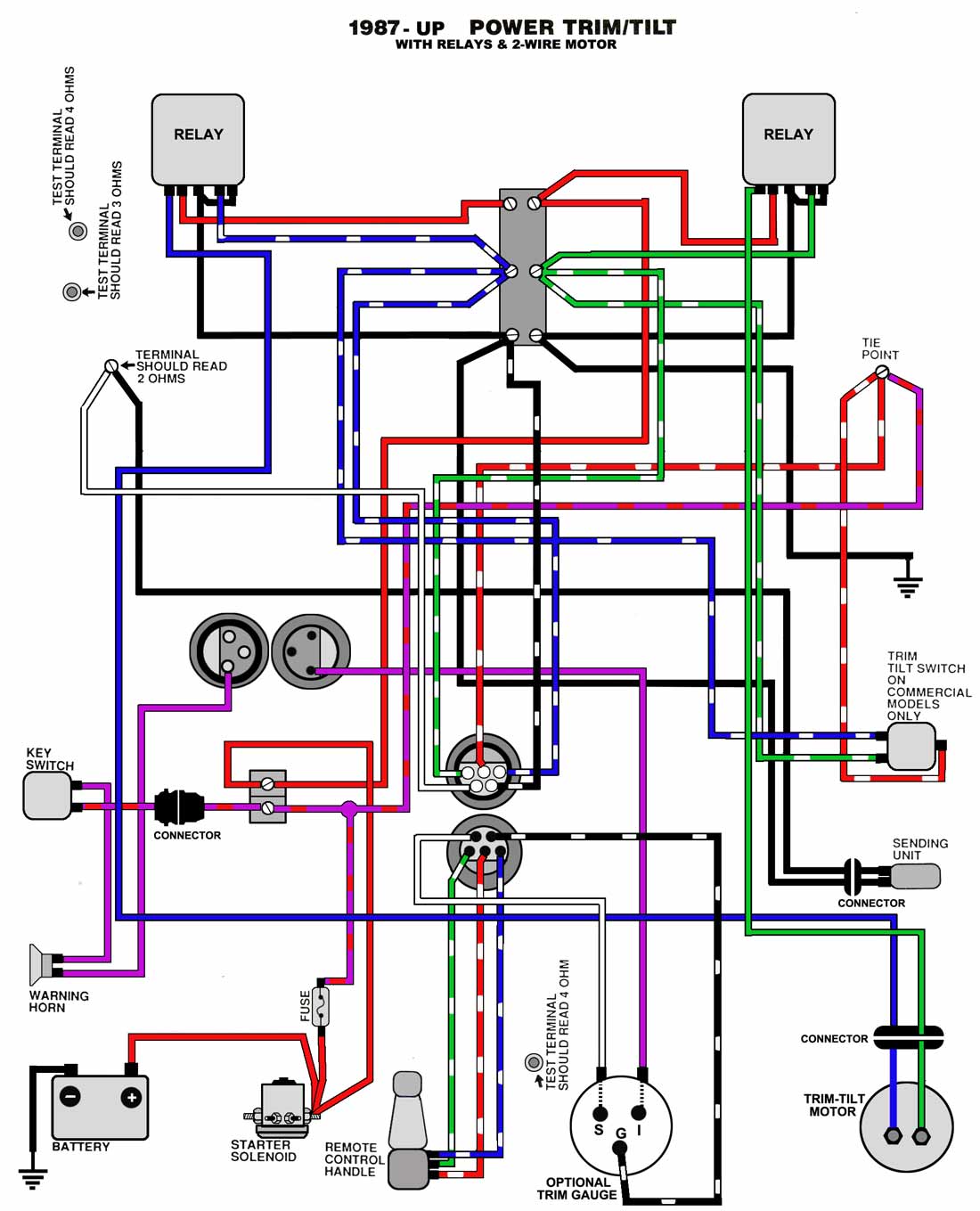
Understanding the Basics of Johnson Outboard Tach Wiring Diagrams
In today's world, being able to understand wiring diagrams and schematics is becoming increasingly important. From home electricians to automotive and marine mechanics, understanding how to read diagrams has become essential. When it comes to outboard motors, using a Johnson Outboard Tach Wiring Diagram can be one of the best ways to get the answers you need.
When it comes to wiring-in a tachometer on your Johnson outboard motor, having an accurate and up-to-date wiring diagram on hand can make the process easier and ensure that the job is done correctly the first time. Let's take a look at some of the features of Johnson Outboard Tachometer Wiring Diagrams so you can be sure you know why they are important and how they will help you when you are wiring up your tachometer.
Color Coding
One great feature of the Johnson Outboard Tach Wiring Diagrams is that they color code the different components of the wiring diagrams. This makes it much easier for you to tell which wires go where and which components they connect to. Color coding also makes it easier to trace back the wiring configuration and identify which terminal the wires should be connected to.
Detailed Diagrams
Another great feature of Johnson Outboard Tach Wiring Diagrams is their level of detail. Each diagram includes all the necessary components, including switches, terminals, lighting coils, potentiometers, and even capacitors. They also indicate where wires from the dash panel, ignition module, and other external drive components need to be connected. This way, you can be sure that you get a perfect connection every time.
Design Specification Labels
The Johnson Outboard Tach Wiring Diagrams also include labels for each component. This allows you to quickly identify the purpose of each component and put it in the correct context with the overall wiring configuration. As you work through the diagram, each label will help you to understand why each component is there and what its function is. This helps to ensure that the wiring is done correctly the first time and avoids issues from miswiring a component.
Takeaways
Johnson Outboard Tach Wiring Diagrams are an important tool for anyone working on wiring for outboard motors. With their color coding, precise diagrams, and detailed specification labels, they offer an easy way to understand the wiring of your outboard motor. By taking advantage of these diagrams you will be well on your way to ensuring that your outboard motor is safely and correctly wired and has all the features that you desire.
I Need A Wiring Diagram For 1976 75hp Stinger Ignition Switch Just Bought This Boat Key Insertion Area Is
Yamaha Mercury Mariner Suzuki Johnson Evinrude Outboards All Models Work Manual For In Listowel Kerry From Apuka 80

Omc System Check Tachometer Instruments 12022 Accessories For Johnson Evinrude Outboards
Tachometer Question Sledder

Evinrude Johnson Outboard Wiring Diagrams Mastertech Marine

Yamaha Digital Multifunction Tach Tachometer Gauge Instrument Display Max Marine Outlet
I Have A 90hp Yamaha Outboard Motor With 703 Control There Are 5 Ea Wires That Go To The Gauges

Mercruiser Inboard Gas Engines Oem Parts Diagram For Wiring Harness Engine Boats Net

Johnson 1980 V4 85hp Tachometer Boating Forum Iboats Forums

Service Manual Dt150 Dt225 Dt200 Dt175 Wiring Diagram 18 Crowley Marine
Fiberglassics Tach Signal Wire 64 Lark Vi Forums

Faria Dress White 4 Tachometer With Systemcheck Indicator 7 000 Rpm Gas Johnson Evinrude Outboard 33150

I Have A 1980 Evinrude V4 140 E140trlcsa The Closest Schematic Can Find For Wiring Looks Like This Don T

Johnson Outboard Tach Wiring Diagram Imglvl

Evinrude Johnson Outboard Wiring Diagrams Mastertech Marine
Yamaha Tachometer Wiring Help The Hull Truth Boating And Fishing Forum

Boat Building Standards Basic Electricity Wiring Your Print Friendly Page

Stringer Wiring