A Comprehensive Guide to Mic Wiring Diagrams
Microphones are a necessary element for various audio applications. Whether it’s in a recording studio, or on the stage or in a broadcasting environment, a solid mic wiring diagram is key to ensuring sound quality and optimized performance. A wiring diagram and the associated elements are critical to having a full understanding of all the components that make up a system and the respective functions they provide. This article explores the details of how to read these diagrams, the settings to adjust, and other considerations to keep in mind when setting up your mic.
What are Mic Wiring Diagrams?
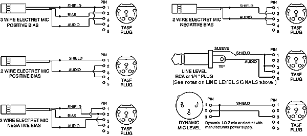
A mic wiring diagram is a visual representation of all the components that make up a microphone-based system. The purpose of this diagram is to enable users to easily identify the components and wires that are common among different microphones and associated accessories. There are two types of wiring diagrams - line drawings and schematic diagrams. Line drawings show which connection points exist and where they need to be connected with physical wires, while schematic diagrams show the overall wiring system layout using an electrical schematic.
Reading a Mic Wiring Diagram
Mic wiring diagrams include symbols that represent the parts in the system. Such symbols represent capacitors, inductors, resistors, switches, ground connections, power lines, and so on. All mic wiring diagrams have a ground symbol at the bottom showing the power source connection. The rest of the symbols will vary according to the type of microphones and extra components used. If the symbols are not labeled clearly, make sure you consult various resources to understand them.
To identify each component, look for text labels next to the symbols for further explanation of their role. It's also important to note that not all connectors depicted in the diagrams represent physical connections. Some diagrams will include phantom connectors (aka "floating" connectors), which signify two nodes that are electrically connected but have no physical connection between them.
Tips & Tricks for Designing Optimal Mic Wiring Diagrams
When creating mic wiring diagrams, it's important to follow a few tips and tricks to ensure that the diagram is easy to read, accurate, and complete. Here are some of the most important ones:
- Pay attention to the physical orientation of components and the arrangement of the symbols.
- Verify that all components will fit in the specified space before drawing the diagram.
- Incorporate grounding connections when building the diagram.
- Draw the connector pins accurately in order to make the correct connections.
- Follow standard conventions when labelling the symbols and connectors.
Conclusion
Mic wiring diagrams are essential tools for ensuring sound integrity and optimal performance of a microphone setup. By understanding the various components and the various symbols used in the diagrams, you can create diagrams that are accurate and complete. Furthermore, following design tips and tricks can help you to design optimal diagrams that can be read and understood easily.

Microphone Wiring Priuschat
Wire Mx391 Mx202 Mx412se Wl18x To 1 8 Connector

Iphone Headphones With Mic Wiring Diagram Headphone Full Size Png Seekpng

Uhf Transmitter 5 Pin Input Jack Wiring
How To Use A Karaoke Microphone Quora

Microphone David Clark Company Wiring Diagram Dc One X Headphones Angle Electronics Png Pngegg
Roadking 56 Truckersreport Com Trucking Forum 1 Cdl Truck Driver Message Board

Copper Talk Turner M 2 U Wiring For 4 Pin Cobra Uniden

Radiomods Hr2510 Mike Wiring Page

Vhf Transmitter 5 Pin Input Jack Wiring

Uhf Transmitter 5 Pin Input Jack Wiring

Microphone And Wireless Transmitter Wiring Countryman Com

Microphone Wiring Diagrams Resource Detail The Dxzone Com

Cobra Mike Pinout

Microphone Wiring Diagram

4 Pin Wiring Help Diagram For Mic Keyswitch Worldwidedx Radio Forum

Microphone Xlr Connector Rca Wiring Diagram Electrical Cable Png 1024x688px Adapter Balanced Line Cylinder
11 Most Por Mic Wiring Diagrams

Microphone Wiring Diagram Shure 577b Sm58 Text Electrical Wires Cable Schematic Png Pngwing

Vhf Transmitter 5 Pin Input Jack Wiring