Horn relay wiring forum main datsun 1200 club bmw diagrams retrofit for first gen 4runners yotatech forums how to wire a horns on mgb and other british cars moss motoring aaw missing chevy tri five 53 12v ford truck enthusiasts thesamba com beetle 1958 1967 view topic motohorn user manual motorcycles an air good electricians advice appreciated electrical instruments by lotuselan net vehicle modification speaker harness set car grille mount blast tone question kawasaki vulcan ase test preparation accessory circuits power windows door locks under repository 21838 next gr 65 circuit diagram help page 2 ih8mud needed triumph rat motorcycle loud scion iq multiple with one switch does work quora hot the touch nastyz28 toyota corolla repair inspection procedure intrusion protection system diagnostics mecatron facebook factory push nc4x4 meishuo mah 4 pin relays jd1912 china electric changeover made in 1964 mustang issue vintage dixie realy capri laser installing high fix replace adjust more stebel nautilus problem suzuki sv650 riders schematics 1 maa2 s 124 d meishuoen kzrider kz z1 z enthusiast tr3 ottawa valley ovtc lights yourmechanic 1r light evshunt wrong photo nasioc headlight please access norton new big dog train american voyager association 34 team bhp 1974 1982 corvette will inc replacement 5 kits

Horn Relay Wiring Forum Main Datsun 1200 Club

Bmw Wiring Diagrams

Horn Relay Retrofit For First Gen 4runners Yotatech Forums

How To Wire A Relay For Horns On Mgb And Other British Cars Moss Motoring
Aaw Horn Relay Missing Chevy Tri Five Forum
53 Horn Relay For 12v Ford Truck Enthusiasts Forums

Thesamba Com Beetle 1958 1967 View Topic Horn Wiring

Motohorn User Manual Motorcycles

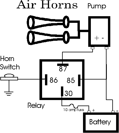
Wiring An Air Horn Good Electricians Advice Appreciated Electrical Instruments By Lotuselan Net

Vehicle Modification 12v Speaker Horn Wiring Harness Relay Set For Car Truck Grille Mount Blast Tone Horns
Horn Wiring Question Kawasaki Vulcan Forum

Ase Test Preparation Accessory Circuits Power Windows Door Locks

Relay Circuits Under Repository 21838 Next Gr

65 Horn Circuit Diagram Ford Truck Enthusiasts Forums
A Horn Relay Wiring Help Diagram Page 2 Ih8mud Forum
Horn Wiring Help Needed Triumph Rat Motorcycle Forums
Loud Horns Page 2 Scion Iq Forums

Multiple Horns With One Switch
Aaw Horn Relay Missing Chevy Tri Five Forum
How Does A Car Horn Work Quora
Horn relay wiring forum main datsun 1200 club bmw diagrams retrofit for first gen 4runners yotatech forums how to wire a horns on mgb and other british cars moss motoring aaw missing chevy tri five 53 12v ford truck enthusiasts thesamba com beetle 1958 1967 view topic motohorn user manual motorcycles an air good electricians advice appreciated electrical instruments by lotuselan net vehicle modification speaker harness set car grille mount blast tone question kawasaki vulcan ase test preparation accessory circuits power windows door locks under repository 21838 next gr 65 circuit diagram help page 2 ih8mud needed triumph rat motorcycle loud scion iq multiple with one switch does work quora hot the touch nastyz28 toyota corolla repair inspection procedure intrusion protection system diagnostics mecatron facebook factory push nc4x4 meishuo mah 4 pin relays jd1912 china electric changeover made in 1964 mustang issue vintage dixie realy capri laser installing high fix replace adjust more stebel nautilus problem suzuki sv650 riders schematics 1 maa2 s 124 d meishuoen kzrider kz z1 z enthusiast tr3 ottawa valley ovtc lights yourmechanic 1r light evshunt wrong photo nasioc headlight please access norton new big dog train american voyager association 34 team bhp 1974 1982 corvette will inc replacement 5 kits
