Understanding the Difference Between Schematic vs. Wiring Diagrams
If you’re an engineer, repair technician, or even a hobbyist, it's essential you understand the difference between schematic vs. wiring diagrams. Read on to learn how to recognize these diagrams, their purpose, and how to apply them in your design or repairs.
Wiring diagrams are important documents and should be kept up-to-date. They form one of the most important parts of any repair or maintenance procedure, providing a comprehensive view of the connections between each component. As such, they should be properly maintained and organized.
What is a Wiring Diagram?
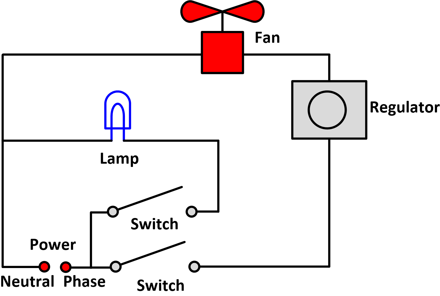
A wiring diagram is a schematic interpretation of the electrical components and connections in a system. It shows the physical layout of the components, the electrical connections between these components and the wires connecting them together. A wiring diagram will indicate components, including the electrical access panel, switchgear, junction boxes, and other components not visible in the circuit board. Wiring diagrams are essential tools used when troubleshooting an electrical system.
What is a Schematic Diagram?
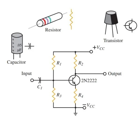
In contrast, a schematic diagram is a graphical representation of the components and interconnections of a system. Like a wiring diagram, it will also show the physical layout of the components, but it does not provide information about the electrical connections that exist between the various components. Instead, it provides a schematic representation of the components, which can help the user understand the workings of a particular system better. Schematic diagrams are often used in the design phase of projects to identify and document the functions performed by individual components.
Comparing Schematic vs. Wiring Diagrams
When comparing schematic vs. wiring diagrams, it is important to keep in mind the different reasons why they are used. Wiring diagrams are intended to illustrate the physical layout of components and routes within an electrical system, while schematic diagrams are used to provide a graphical overview of the functions of various components within a system.
Another key difference between these diagrams is that wiring diagrams are more detailed in nature and must include specific measurements for the components listed. On the other hand, schematic diagrams use symbols and visuals to depict the components in a system and the interconnections between them without the need for any specific measurements.
Finally, wiring diagrams are used to provide a means of tracing individual electrical circuits and allow users to properly trace and diagnose faults, while schematic diagrams are mainly used in the design process and provide a useful aid in designing a system or troubleshooting existing systems.
Benefits of Using Wiring Diagrams and Schematic Diagrams
Using wiring diagrams and schematic diagrams has numerous benefits that allow engineers, technicians, and hobbyists to work more accurately and efficiently. A wiring diagram can quickly show you how each circuit is connected and how each component is wired in the system. Likewise, a schematic diagram will give you an overall view of the workings of the system, streamlining the trouble-shooting process.
Ultimately, both wiring diagrams and schematic diagrams are essential tools for understanding the complete operation of an electrical system and are invaluable for design and troubleshooting. Knowing when to use each of these diagrams and how to explain complex wiring diagrams can enable anyone to become a more efficient and accurate worker.

Plc Training Reading Electrical Wiring Diagrams And Understanding Schematic Symbols Tw Controls

Wiring Diagram Electrical Wires Cable Schematic Drawing Harley Sdometer Angle Electronics Text Png Pngwing

Electronics Drafting Wiring Diagrams

Electrical Schematic Diagram Elementary Wiring A2z
Electrical Schematic Diagram Of The Clamp Control System Scientific

Electrical Diagrams And Schematics Inst Tools

Wiring Diagram Circuit Schematic Clothes Dryer Electrical Network Receptacle Angle Electronics Text Png Pngwing

How To Construct Wiring Diagrams Controls

Wiring Diagram Everything You Need To Know About
What Is The Difference Between A Circuit Diagram And Ladder Quora

Electronics Drafting Wiring Diagrams

A Infi Ltrometer Stand And B Schematic Wiring Diagram To Connect Scientific
Lh E

How To Read And Understand An Electrical Schematic

How To Read An Electrical Wiring Diagram Inst Tools

Battery Charger Ipad Mini Schematic Wiring Diagram Usb Png 2845x1200px Area Auto Part Black

How To Read Electrical Schematics Circuit Basics

Wiring Diagram A Comprehensive Guide Edrawmax Online

Ladder Diagram Schematic Wiring Electrical Academia
