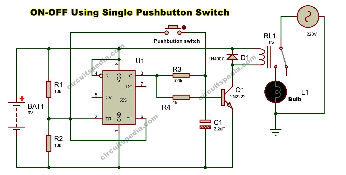
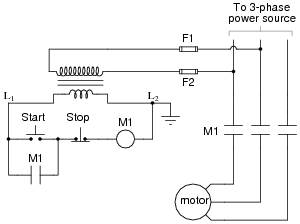
What is a Start Stop Wiring Diagram with One Switch?
A start stop wiring diagram with one switch is a type of electrical circuit that utilizes one switch to start and control the running of the motor. This type of wiring diagram is often used in applications such as elevators, conveyors, recirculating pumps, and escalator systems. Essentially, it is a type of circuit that starts and stops machines automatically by switching on or off the power supply to the machine. It is beneficial because it saves time and energy when compared to manual operations.
When it comes to creating a start stop wiring diagram with one switch, understanding electrical diagrams is an important factor. Knowing how to read the diagram will allow for easier setting up and troubleshooting. The diagram must clearly show the connection of the different parts of the circuit, such as the switch, controller, motor, and power supply so that understanding the overall functioning of the circuit can be made easier.
Purpose of Start Stop Wiring Diagrams
Start stop wiring diagrams are designed to provide simple, reliable automation of motors. When correctly configured, these diagrams keep motors powered when they are needed and prevent them from running when not required, thus ensuring efficiency and safety. Different applications such as elevators, pumps, and factory machinery often require their own start stop wiring diagram, as each application requires specific voltage and current levels that may even be different depending on the need.
Essential Components of Start Stop Wiring Diagrams
Start stop wiring diagrams for with one switch typically include the following essential components:
- Controller - controls the entire circuit and initiates motor running when switched on.
- Switch - the switch turns on or off the electrical circuit depending on whether the starting or stopping signal has been given.
- Motor - rotates when supplied with power.
- Power Supply - supplies an alternating current to the motor.
Steps to Set Up a Start Stop Wiring Diagram with One Switch
When setting up a start stop wiring diagram with a one switch, certain basic steps must be followed. These are:
- Fully understand the specific requirements for the particular application.
- Connect the power supply correctly.
- Connect the switch according to the schematic diagram.
- Connect the motor wires and other equipment as instructed.
- Test the circuit repeatedly.
- Make sure the motor runs properly and without any faults.
Benefits of Start Stop Wiring Diagrams
Start stop wiring diagrams provide major benefits including:
- Saving time and energy from manual control.
- Increased operational efficiency.
- Reduction in maintenance costs.
- Enhances safety since there is no risk of operator error.
- Increases consistent productivity.
Conclusion
Start stop wiring diagrams with one switch are a convenient and efficient way of controlling the running of motors. They require a thorough understanding of electrical diagrams and wiring configurations, but once correctly set up can provide many benefits to operations such as cost savings, enhanced safety, and increased efficiency.

Start Stop Circuit What They Are Where And How To Wire

Float Switch Installation Wiring Control Diagrams Apg

Motor Control Circuit Wiring Inst Tools

Reverse Motor Starters

Understanding Three Wire Control Technical Articles

Motor Control Circuits Ladder Logic Electronics Textbook

How To Convert A Basic Wiring Diagram Plc Program Realpars
Dont Know How To Wire A Start Stop Switch Motor Diy Home Improvement Forum
How Do I Operate A Star Delta Starter With 2 Wire Control Schneider Electric Uk

Two Wire Control Circuits

Sequence Controls For Motor Starters
4 Way Switch Wiring Diagrams Do It Yourself Help Com

Push Ons And Control Stations Pilot Devices

Single Push On Off Latch Switch

Control Wiring 3 Wire Start Stop Circuit Tw Controls

Float Switch Installation Wiring Control Diagrams Apg

Main And Auxiliary Circuit Diagrams Of Switching Three Phase Motors Via Contactor Directly Eep

Start Stop Circuit What They Are Where And How To Wire

Ac Motor Control Circuits Worksheet Electric
