Submersible Pump Control Box Wiring Diagram Pdf: Everything You Need to Know
Wiring diagrams are essential components of any electrical or electronic device. They provide a visual representation of the connections between the components of the device, helping users to understand how the parts fit together. With a submersible pump control box, the wiring diagram is even more important - it helps to ensure that the pump control box is wired correctly and safely.
In this article, we will take a look at what submersible pump control box wiring diagrams involve, why they are necessary, and how to properly read them. We will also discuss the various types of wiring diagrams available, as well as safety considerations when it comes to using a submersible pump control box. By the time you finish reading, you will have a better understanding of how to use and read wiring diagrams for your submersible pump control box.
What Is a Submersible Pump Control Box Wiring Diagram?
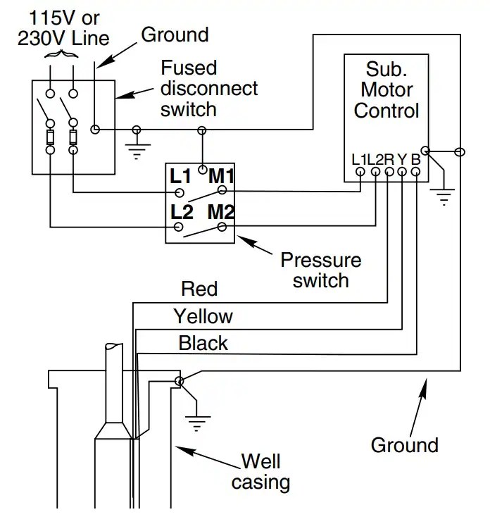
A submersible pump control box wiring diagram is a diagram that shows how the wires should be connected in order to properly control a submersible pump. It provides a visual representation of the connections between all the components, such as the control panel, safety switch, disconnect switch, and so on.
The wiring diagram will show where the wires go from the pump control box to other components like the water system. The wiring diagram should also include all the necessary connections for power supply and grounding, as well as any additional requirements that might be needed.
Why Are Wiring Diagrams Important?
When installing a submersible pump control box, it's important to make sure that the wiring is connected correctly in order to ensure maximum safety and efficiency. If a wire is incorrectly connected or if there is an error in the wiring diagram, then the pump may not work correctly – which can result in costly repairs or even the need to replace the unit altogether.
A wiring diagram can be used to double-check whether the wiring has been done correctly, as well as to troubleshoot electrical problems. It can help to prevent costly mistakes and can save time by quickly locating any errors that might have occurred.
How Can I Read a Submersible Pump Control Box Wiring Diagram?
Reading a submersible pump control box wiring diagram can be a bit tricky, as it involves understanding what each component does and how it works. However, with a little bit of practice, anyone can learn how to read these diagrams.
Start by understanding the components – learn what each component does and how it fits into the larger circuit. Next, take a look at the wiring diagram itself. Note the labels that indicate the connection points between the components, and follow them in order. If a component has multiple connections, trace all the wires to make sure that they are connected properly.
Types of Wiring Diagrams
There are many different types of wiring diagrams available, each of which has its own purpose. Printed wiring diagrams, for example, usually contain detailed technical information about how the device works, while schematic diagrams provide a simplified view of the circuitry.
Flow diagrams are another type of wiring diagram that t show the flow of data between the components. They are helpful in troubleshooting problems and identifying certain patterns within the circuit.
Finally, wiring diagrams can be used to show the physical layout of all the components. This type of diagram includes a map, for example, that indicates the actual positions of the components on the board.
Safety Considerations
Safety is always a priority when dealing with electrical devices and wiring. Before connecting any wiring to your submersible pump control box, always check the polarity of the terminals (make sure the positive and negative terminals are the correct way around), and double-check that all of the wires lines up with the wiring diagram.
Additionally, be sure to properly secure any wiring that's connected to the pump control box, as loose wires can cause short circuits and other potentially dangerous issues. And of course, never touch a live electrical current, unless you are absolutely sure that it is safe to do so.
Conclusion
Submersible pump control boxes require careful wiring in order to operate correctly and safely. The wiring diagram included with the pump control box is an essential tool that helps you to understand how the parts should be connected and how they interact with each other. With a bit of practice, anyone can learn how to read and use a wiring diagram for a submersible pump control box. Make sure you take all necessary safety precautions when working with electricity, and you'll have no problems getting your pump control box running smoothly in no time.

Water Pump Wiring Troubleshooting Repair Diagrams

Using Vlt Aqua Drive In Submersible Pump Application

Dayliff Sunverter 3 Ac Solar Pump Controller Davis Shirtliff Group

Water Pump Wiring Troubleshooting Repair Diagrams

Off Grid Homestead Solar Wiring Diagram Tiny Shiny Home

Float Switch Installation Wiring Control Diagrams Apg
Auto Restart Pump Control

Soft Starter For Potable Water Well Pump Wiring Diagram Troubleshooting Example Eep

Honda City Passenger Fuse Diagram Manuals

Installation And Operating Manual Dab Pumps Water Pages 1 15 Flip Pdf Fliphtml5

Mazda Car Pdf Manual Wiring Diagram Fault Codes Dtc

50a Control Panel 30 Gallons

Eco Flo Efcb5 Hd Well Pump Control Bo Instruction Manual Pdf
Cu 301 96436754 Grundfos

Submersible Pump Wiring Diagram Control Panel Pumping Station Microcontroller Pumps Transpa Png

How To Install And Wire A Well Pump Installation Guide

Float Switch Installation Wiring Control Diagrams Apg

Choosing The Right Water Well Pump Er S Guide

The Red Jacket Submersible Turbine Pump Veeder Root

Aim Manual Page 54 Single Phase Motors And Controls Motor Maintenance North America Water Franklin Electric