What to know about thermostat wire color codes syston cable system is on wiring how 2 3 4 5 guide nest with trane heat pump doityourself com community forums do i my sensi ca for mach8 bat a c 99 vectra winnebago owners online need common diagram electrical technology 230v 240v 120v ac single element installation tutorial https www electricaltechnology org 2020 01 water heater html facebook explained fast stat 1000 and maker simple diy home improvement forum install settings vine smarthome refrigerator connection full electric practical fully4world 110v aprilaire 500 humidifier hd png kindpng has three wires am compatible ecobee code making hvac problem solver coleman mach you hook it up mod instructions sci usa etn 24 super smart won t power only two or connected the installing adapter customer support everything honeywell wonderful bright built relay transpa 2370x1391 free nicepng help wyze 6001261 pinpng replacing analog digital forest river battle own hacking skirmish question simplified block diagrams tips tricks car circuit air conditioner fan etechnog duo therm 1994 georgie boy irv2 best 54 off ingeniovirtual goodman size seekpng set ohmefficient conventions thermostatic principles function missing add options zone valve heating wall

What To Know About Thermostat Wire Color Codes Syston Cable System Is On

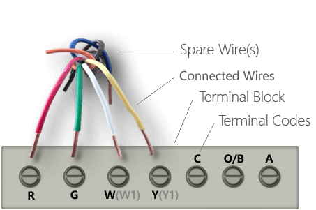
Thermostat Wiring How To Wire 2 3 4 5 Guide

Nest Thermostat Wiring With Trane Heat Pump Doityourself Com Community Forums

How Do I Wire My Thermostat Sensi Ca
Thermostat Wiring For Mach8 Bat A C 99 Vectra Winnebago Owners Online Community

Thermostat Wiring Do I Need A Common Wire C
Thermostat Wiring Diagram
Electrical Technology 230v 240v 120v Ac Single Element Thermostat Wiring Diagram Installation Tutorial Https Www Electricaltechnology Org 2020 01 Wire Water Heater Html Facebook

Thermostat Wiring Explained

Fast Stat 1000 And Common Maker Installation Guide Simple
Thermostat Wiring For Heat Pump Diy Home Improvement Forum

How To Install A Thermostat

Heat Pump Thermostat Wiring Settings Vine Smarthome

Refrigerator Thermostat Connection And Full Electric Wiring Diagram With Practical Fully4world

110v Thermostat Wiring Diagram Nest Aprilaire 500 Humidifier To Hd Png Kindpng

My Thermostat Has Three Wires Am I Compatible With Ecobee

Guide To Thermostat Wiring Color Code Making Install Simple And Fast

Hvac Problem Solver

Coleman Mach Thermostat Wiring Diagram How Do You Hook It Up
What to know about thermostat wire color codes syston cable system is on wiring how 2 3 4 5 guide nest with trane heat pump doityourself com community forums do i my sensi ca for mach8 bat a c 99 vectra winnebago owners online need common diagram electrical technology 230v 240v 120v ac single element installation tutorial https www electricaltechnology org 2020 01 water heater html facebook explained fast stat 1000 and maker simple diy home improvement forum install settings vine smarthome refrigerator connection full electric practical fully4world 110v aprilaire 500 humidifier hd png kindpng has three wires am compatible ecobee code making hvac problem solver coleman mach you hook it up mod instructions sci usa etn 24 super smart won t power only two or connected the installing adapter customer support everything honeywell wonderful bright built relay transpa 2370x1391 free nicepng help wyze 6001261 pinpng replacing analog digital forest river battle own hacking skirmish question simplified block diagrams tips tricks car circuit air conditioner fan etechnog duo therm 1994 georgie boy irv2 best 54 off ingeniovirtual goodman size seekpng set ohmefficient conventions thermostatic principles function missing add options zone valve heating wall

