The Importance of Understanding Wiring Diagram for Start Capacitor
Wiring is an essential aspect of any electronic or electrical system. It is the process of connecting various components together to create a functional circuit, allowing the flow of electricity. Proper wiring is crucial for the efficient and safe operation of devices and equipment. Without proper wiring, devices can malfunction, resulting in damage or even fire hazards. And when it comes to wiring, understanding the diagram is a crucial step that cannot be overlooked. In this article, we will discuss the importance of understanding the wiring diagram for start capacitors and how it plays a significant role in the functioning of electronic devices.
What is a Start Capacitor?
A start capacitor is a type of electrical component used in motors and other devices to provide an initial boost of power to help start the motor. It stores electrical energy in the form of an electrostatic field and then releases it to the motor when needed. Start capacitors are often used in single-phase motors, which are commonly found in household appliances like refrigerators, air conditioners, and washing machines.
The Role of Wiring Diagram in Understanding Start Capacitor
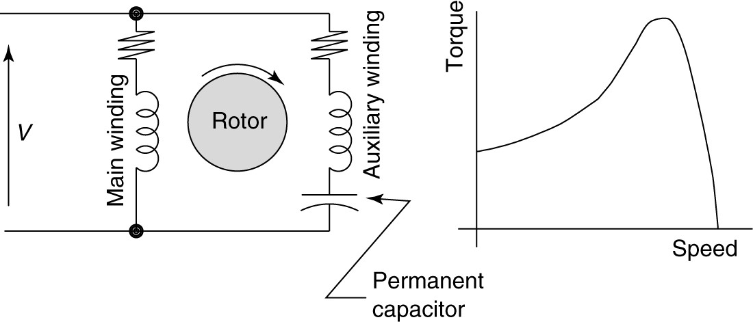
A wiring diagram is a visual representation of the connections between various components in an electrical system. It shows the physical layout of wires and components, as well as their connections and the flow of electricity. In the case of start capacitors, the wiring diagram plays a crucial role in understanding the correct connection of the capacitor within the circuit. It helps to ensure that the capacitor is connected correctly, as improper installation can lead to malfunctions or even damage to the device.
Understanding the wiring diagram for start capacitors is especially important in situations where a replacement capacitor is needed. In these cases, the exact model and specifications of the original capacitor may not be available. By understanding the wiring diagram, one can identify the correct terminals and connections required for the replacement capacitor, ensuring proper functioning of the device.
Common Symbols Used in Wiring Diagrams
Wiring diagrams use standardized symbols to represent different components and connections. Familiarizing oneself with these symbols is essential in understanding the diagram accurately. Some common symbols used in wiring diagrams are:
- Resistor: Represents a component that resists the flow of electricity
- Capacitor: Represents a component that stores electrical energy
- Switch: Represents a device or mechanism that controls the flow of electricity within a circuit
- Battery: Represents a power source
- Ground: Represents the connection to the earth, providing a safe path for excess electricity
Step-by-Step Guide to Understanding a Wiring Diagram for Start Capacitor
Understanding a wiring diagram may seem daunting at first, but it becomes more manageable by breaking it down into smaller steps. Here is a step-by-step guide to help you understand a wiring diagram for start capacitors:
- Identify the start capacitor in the diagram and determine its location within the circuit.
- Note the symbols used to represent the capacitor and its connections.
- Identify any other components involved in the circuit, such as switches or motors.
- Follow the lines connecting the components to determine their connections.
- Make note of any color coding or labeling on the wiring diagram, as it may help in identifying specific wires or terminals.
- Ensure that the connections shown in the diagram match the physical connections of the circuit.
By following these steps, one can easily understand a wiring diagram for start capacitors and their connection within the circuit.
In Conclusion
Wiring diagrams are fundamental in understanding the proper connections for electrical components within a circuit. When it comes to start capacitors, understanding the wiring diagram is crucial in ensuring their correct placement and functioning within the circuit. By familiarizing oneself with the symbols and following a step-by-step process, one can easily understand and interpret a wiring diagram for start capacitors. Proper installation and understanding of the diagram not only ensure the efficient operation of devices but also prevent any potential hazards.

Transformers Phase Converters And Vfd 5 Hp Motor Capacitor Question Practical Machinist Largest Manufacturing Technology Forum On The Web

Ecn Electrical Forums

Types Of Single Phase Induction Motors Motor Wiring Diagram Electrical Academia

Hard Start Kit Capacitor Compressor For Air Conditioning Assist 5 2 1 Saver 521

Replacing Your A C Run Capacitor 8 28 20 Where S Blake

China Ceiling Fan Wiring Diagram Capacitor Cbb61 Motor Starting Start Run

Single Phase Motor Capacitor Start Sparkyhelp

Permanent Split Capacitor Motor Connection Diagram For Multiple Sds Wiring Multi Sd With

Can You Use Two Single Capacitors Instead Of One Dual Capacitor Powerwell

Motor Capacitor Electric Wiring Diagram Ac Png 3156x2128px Watercolor Cartoon Flower Frame Heart
Hvac Talk Heating Air Refrigeration Discussion

Single Phase Cap Start Run Motors Rotor Uk

Wiring Diagram Single Phase Electric Power Electrical Wires Cable Motor Capacitor Circuit Rectangle Xuandong Start
Fixed Ffre1233s1 Frigidaire Window Ac Help Wiring A C Er Motor Applianceblog Repair Forums

Capacitor Start Motors Diagram Explanation Of How A Is To Single Phase Motor Bright Hub Engineering

Motor Start And Run Capacitors

Wire Ring A 240 V Single Phase Motor And Capacitor Electronics Forum Circuits Projecticrocontrollers

What Does A Capacitor Do

Cbb60 Capacitor