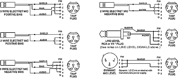
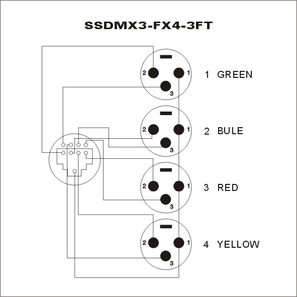
Understanding Xlr Mic Wiring Diagrams and What They Mean
It can be both intimidating and fascinating to look at a wiring diagram for an Xlr mic. It's like trying to decode a secret language, a map that can help you gain an understanding of the equipment and its connections. However, if you take the time to learn how to interpret a wiring diagram, you'll soon be able to figure out the components and how they fit together to complete a circuit. In this article, we’ll explain the basics of wiring diagrams and what Xlr mic wiring diagrams symbolize.
Wiring diagrams contain symbols to represent electrical components; these can be anything from basic resistors and power sources to complex integrated circuits. The symbols are labeled to show which parts are connected in each particular section. The different parts of a wiring diagram can vary depending on the type of wiring system being depicted. A typical wiring diagram, such as those found in most commercial applications, will generally include a Ground symbol or Ground connection symbol.
Understanding The Different Components Of An Xlr Mic Wiring Diagram
An Xlr mic wiring diagram consists of several components, all of which need to be connected in order to make a complete circuit. First, there is the microphone itself. This component is typically designated by a symbol with a circle in the center. This is followed by a signal line, usually depicted by a dashed line connecting two components. The signal line carries the electrical signal from one point to another. Next is the amplifier. It can be shown as a rectangle or cube with a number of lines pointing towards it. This represents the sound signal going into the amplifier before being sent out to speakers or other audio devices.
Identifying Connectors On An Xlr Mic Wiring Diagram
In addition to the components themselves, an Xlr mic wiring diagram usually includes several connectors. These are typically depicted as circles with arrows coming off of them, indicating the direction of the connection. These connectors are used to transfer electricity and signals between components and can range from basic single-pin connectors to specialized dual-channel Xban-style connectors. When connecting multiple components, the arrows must be followed so that the connections are correct.
Learning How To Read And Interpret An Xlr Mic Wiring Diagram
To effectively use an Xlr mic wiring diagram, it helps to have a general knowledge of what the various symbols stand for and how each one relates to the other. With some practice, you will eventually become familiar with the symbols and be able to understand the relative positions and connections between each part of the circuit. Similarly, you should also get an idea of how the various connectors are used to link components together.
Once you have a basic understanding of the wiring diagram, you can begin actually following the flow of signals through the circuit by starting at the microphone and tracing outwards from there. This process helps to gain an overall understanding of how the components and connectors work together. With a little practice, soon you'll be fantastically proficient at reading and interpreting Xlr mic wiring diagrams.
Xlr To Jack Adapter Phase Issue Digital Talk Forum Photography Review

Pinouts And Wiring Diagrams For Cables Sync

Shure Sm58 Microphone Wiring Diagram Xlr Connector Png Clipart Angle Area Auto Part Black And White

How To Build Your Own Xlr Cables A Step By Guide Studio Diy The Home Archive

Tape Op Stereo Mic Wiring Message Board

Charging Cable For Wheel Chairs And Electric Bicycles That Use The 3 Pin Xlr Microphone Connector

Xlr Over Cat5 Balanced Mic Level Line Audio Cat5e Cabling Jeff Geerling

Vhf Transmitter 5 Pin Input Jack Wiring

Convert From Ta4f To Ta5f Mini Xlr At Dvinfo Net

Connector Pinout Drawings Clark Wire Cable

Flex 3000 To 3 Pin Female Xlr Audio Interface Configuration

Microphone And Wireless Transmitter Wiring Countryman Com

Xlr Over Cat 5 6 7

Microphone Shure Sm58 Xlr Connector Wiring Diagram Pinout Angle Png Pngegg

Everything You Need To Know About Microphone Phantom Power Acoustic Guitar

Comm 4 Pin Xlr Connector Wiring Diagram Inside The Mind Of Sators
How Can I Connect My Mono Microphone Xlr Output To A Stereo Trs Socket

Wireless Microphone Schematics Point Source Audio