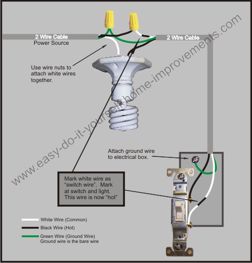
What You Need To Know About Basic Household Wiring Diagrams
Electrical wiring diagrams are a visual representation of the physical connections and layout of an electrical system. These diagrams show how the components of a system are interrelated and can indicate the presence of voltage changes or current flow in a given circuit. Basic wiring diagrams, or single-pole wiring diagrams, are used to show electrical circuits that are relatively simple, and typically contain one to three wires or cables. From single-pole wiring diagrams, more complex circuits can be built. Understanding wiring diagrams is essential for anyone who works with electricity, so it pays to learn the basics.
Having a good knowledge of wiring diagrams is essential for electricians, plumbing professionals, construction workers, and even homeowners. Wiring diagrams help installers and maintenance personnel to determine the best way to connect, disconnect, and replace different devices. They also make it easy to troubleshoot electrical problems, such as open circuits and shorts. Knowing how to read basic household wiring diagrams can give you the ability to inspect and repair electrical issues in your own home.
The Anatomy Of Basic Wiring Diagrams
Wiring diagrams can appear to be daunting at first glance; however, they are composed of several basic components. Standardized symbols and lines mark the connections between the various components. The most common symbols are used to represent common components such as switches, lights, outlets, and receptacles. Interlocking black lines represent connection points where two or more wires terminate.
To understand a wiring diagram, there are three main components which parts are represented. The first is the power source. In a wiring diagram, the power source is denoted by a long vertical line with a solid line at the bottom and a dotted line at the top. This indicates the possibility of running either single-phase or three-phase power.
The second component is the load, which is represented by a lighter line with a solid line at the bottom and a dashed line at the top. The load is often a receptacle, light switch, or some other type of device. This is what will be powered by the incoming power.
The third and final component is the control circuit and this is usually represented by dots and dashes with circles located around them. This indicates that something needs to be controlled, typically with a power switch. Wiring diagrams provide a basic map of the circuits, indicating the flow of electricity between devices.
Common Symbols On Wiring Diagrams
Knowing how to interpret wiring diagrams is essential for accurately diagnosing electrical issues. Most standard wiring diagrams use standardized symbols to represent the various components that make up a circuit.
Below is a table showing a few of the most commonly used symbols:
| Symbol | Meaning |
|---|---|
| SW | Switch |
| L/L1, L/L2, etc. | Load/Light |
| R/R1, R/R2, etc. | Receptacle/Outlet |
| N | Neutral |
| G | Ground |
| F | Fuse |
| C | Conductor |
| MCB | Miniature Circuit Breaker |
Once you’re familiar with the symbols, it’s much easier to interpret a wiring diagram. Keep in mind though that there are multiple versions of wiring diagrams, so it’s important to use the correct one for the job. If in doubt, consult with a professional electrician or another qualified person.
How To Get Started With Basic Household Wiring Diagrams
Getting started with understanding basic wiring diagrams doesn't need to be difficult. With an understanding of the symbols used, and practice, you’ll quickly get to grips with creating and reading basic wiring diagrams. Consider investing in an introductory guide to electrical wiring systems, or reference an online resource. Taking a course in basic electrical wiring is another option if you're looking to complete more advanced projects.
It's important to always stay safe when working with electricity, so be sure to adhere to the proper safety precaution when learning about wiring diagrams and working on any electrical-related tasks. This could include obtaining necessary permits, using the appropriate tools such as insulation-protected wire strippers and screwdrivers, and ensuring all electrical parts are up to code.
Following the advice above, you’ll soon be adept at reading basic wiring diagrams. This knowledge can come in handy in a variety of scenarios; whether you’re replacing electrical components, troubleshooting problems, or installing a new device. Understanding wiring diagrams is an essential part of being able to work with electronics safely and effectively.
Electrical Technology Basic Home Wiring Diagrams Tutorials Https Www Electricaltechnology Org 2013 09 Html Facebook

Resources

Resources

Types Of Electrical Wiring

How A Home Electrical System Works

How To Wire A 3 Way Switch Wiring Diagram Dengarden
Basic Room Electrical Wiring Diagram Fourzon Graphics Facebook

Light Switch Wiring Diagrams

Wiring Diagram Software Free Online App

Wiring Basics For Residential Gas Boilers Achr News

Wiring Diagrams

The Complete Guide To Electrical Wiring Eep

Light Switch Wiring Diagram

Simple Motorcycle Electrical Wiring Diagram For Android

How To Construct Wiring Diagrams Controls

Wiring A Light Switch

Wall Outlet Wiring Diagram

Wiring Diagram Software Free Online App

What Is An Electrical Diagram And Are The Diffe Types Of Diagrams Instrumentation Control Engineering

