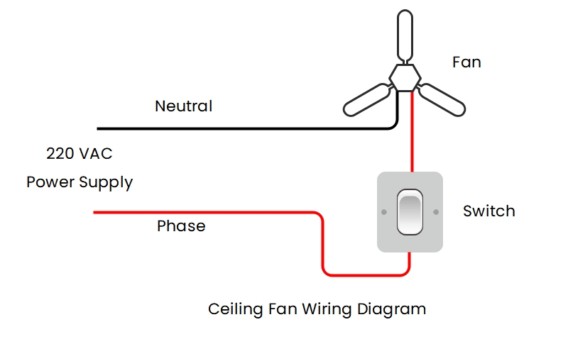
Ceiling Fan Electrical Schematic: All You Need to Know About Wiring Diagrams
Installing a new ceiling fan can provide countless hours of bedroom or living room relaxation, not just for the summer nights but for 365 days. In fact, it is even more efficient than air conditioning in some cases, since it does not contribute to the strain of your energy bills. However, before you actually get your hands dirty and start installing the fan of your dreams, you must know the basics of wiring diagrams, an important part of any electrical installation. Without a proper understanding of these diagrams, it might be difficult to wire up your ceiling fan correctly.
Wiring diagrams are not just a roadmap depicting the electric components, they are an intricate routing of electrical power that allow electricians to map out their objectives with precision. Ceiling fan electricians schematics work in similar ways - they show how the components need to be wired up, and the order in which they should be connected.
Anatomy of a Wiring Diagram
Every wiring diagram’s anatomy comprises of five essential components, namely the connections, ground points, switches, bulbs and pins. The connections are the lines that illustrate the physical connection between components. These lines might be straight or curved with arrows indicating direction. Ground points are symbolized by small zigzag lines which indicate the path of the live current from one circuit to another. Switches are symbolized by the letter “S” and are placed in the middle of two or more lines indicating the current path. Bulbs are represented by circles with a number written in the middle. Pins consist of small black squares; they contain the same voltage and current values as the switches.
How a Ceiling Fan Works?
A ceiling fan usually consists of four main components, the motor, the blades, a capacitor and the switch. A ceiling fan rotates by creating a spinning force on the fan's blades, known as thrust, which is generated by the flow of energy through the fan's motor. This energy is delivered to the motor by a capacitor, in the form of electrical current. Since the motor has multiple starting and running speeds, the capacitor is responsible for controlling them. It works by receiving the current from the fan switch, whereupon it generates either low, medium or high speed depending on how much current is going through the capacitor.
Understanding Ceiling Fan Electrical Schematics
To understand a ceiling fan electrical schematic, one must first understand the wiring diagram symbols. These symbols represent individual components such as switches, outlets, and lights. They also show the order in which those components should be connected and the direction of the current flow. To interpret the diagram fully, you must be able to distinguish between switches and outlets. Once you have done this, you will be able to identify the color of the wires and connect them properly.
The next step is to make sure all of the wiring runs according to the directions of the ceiling fan manufacturer. This means running the feeder wire from the switch to the fan, the switch and the fan housing. Additionally, ensure that the branch circuit wires are installed correctly, too. The last step is to hook everything up correctly to the main breaker panel and the wall receptacle, in accordance with building codes.
Conclusion
Ceiling fan electrical schematic diagrams can seem intimidating at first glance, but if you take the time to learn them and follow the instructions indicated by the manufacturer, you will be able to successfully install a ceiling fan that not only looks great and adds ambience, but also keeps you comfortably cool when the summer heat hits.

Ceiling Fan Wiring Diagrams
Ceiling Fan Light Kit Wiring Diagrams Do It Yourself Help Com

Ceiling Fan Wiring Diagrams

Wire A Ceiling Fan

Wiring Diagram Ceiling Fans Motor Capacitor Electric Fan Angle Text Png Pngegg

Wiring Diagram A Comprehensive Guide Edrawmax Online

Wire A Ceiling Fan
Ceiling Fan Light Kit Wiring Diagrams Do It Yourself Help Com

Ceiling Fans

How Is A Ceiling Fan Wired Quora

How To Make Connection Of Ceiling Fan With Diagram Learn Electrician

Wiring A Ceiling Fan And Light With Diagrams Ptr

Ceiling Fan And Light Wiring Circuit Diagram

Ceiling Fan Wiring Diagrams

How To Connect Ceiling Fan Wires With Pictures Wikihow

How To Connect Ceiling Fan Wires With Pictures Wikihow
Ceiling Fan Light Kit Wiring Diagrams Do It Yourself Help Com

Ceiling Fans

Ceiling Fan Sd Switch Repair


