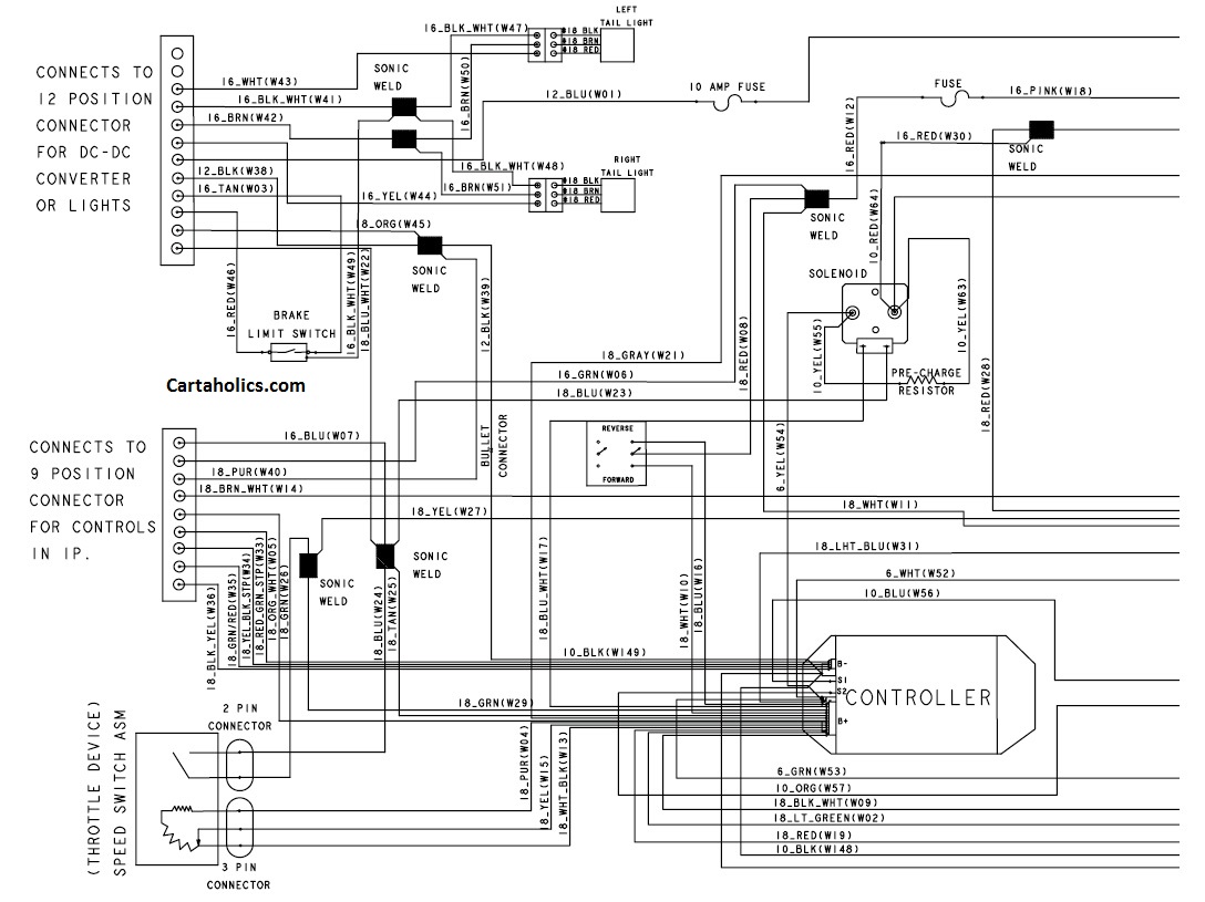
Everything You Need to Know About Electric Vehicle Wiring Diagrams
As electric vehicles become more popular, being able to understand and interpret the wiring diagrams associated with them is essential. Not only are these diagrams important for helping to troubleshoot issues, but they can also provide a valuable resource for figuring out how various components are connected within a vehicle. In this article, we will discuss the basics of electric vehicle wiring diagrams, and explain how they can make your life easier.
The most important thing to consider when trying to understand a wiring diagram is the symbols used in it. Each symbol represents a certain component or connection, and understanding what each of these symbols means is key to being able to interpret the diagram properly. Once you’ve got a handle on the symbols and their meanings, you will be in a much better position to idenitify different parts of the wiring diagram, and make any necessary connections.
Electric Vehicle Connections Basics
Before we look at the electric vehicle wiring diagram itself, it’s important to understand the basics of vehicle connections. Generally speaking, the wiring diagram will show each of the main vehicle systems, along with the components that make them up. From here, you can easily identify which components are required for the system to function correctly, and then use the symbols on the diagram to connect them appropriately.
For example, a typical electric vehicle wiring diagram may show the battery, controller, motor, and any other components that are needed to make the system run efficiently. These components will all be identified by symbols, with lines connecting them to show how they are wired together. In some cases, an additional component such as a switch may be present in the diagram, to provide a reference point where separate wiring networks can intersect.
Understanding Negative and Positive
When reading a wiring diagram, it’s important to know what the symbols for negative and positive signify. Generally speaking, the negative symbol will be represented by a minus sign (-), while the positive symbol will be represented by a plus sign (+). Both of these symbols should be located near the component that is meant to receive the power.
In addition, you should also be aware of the ground wires, which are usually represented by a circle or line with three dots. These wires play an important role in maintaining the power both safely and securely, so it’s important to make sure that they are connected to one or more of the indicated components in the wiring diagram.
Identifying Wire Colors
In addition to understanding the symbols on an electric vehicle wiring diagram, it’s also important to know the colors of the wires that are plugged into the various components. Identifying the color of the wires is a key part of being able to correctly connect the components, so it’s worth familiarizing yourself with which colors go with which components. Generally speaking, the main wire colors are red (for positive), black (for negative), and green (for ground). However, other wire colors may be present depending on the type of vehicle, so it’s a good idea to check the manufacturer’s documentation for the specific colors used in your vehicle.
Conclusion
Being able to interpret electric vehicle wiring diagrams is an important skill for anyone who owns or works on such vehicles. By understanding the differences between symbols and colors, you can easily follow the diagrams and make any necessary connections. Additionally, it’s worth ensuring that all wires are connected appropriately to avoid any potential damage or safety issues. With the right knowledge, you can make sure that your vehicle runs at optimum efficiency and stay safe and secure on the road.

Wiring Diagram Car For Android

Motor Controller Electric Electrical Wires Cable Wiring Diagram Vehicle Curtiss Motorcycles Png Pngegg

Wiring Diagrams For Cars Trucks Suvs Autozone

An Engineer S Introduction To Electric Vehicles Evs

Basics Of Automotive Electrical Circuits

Club Car Ds Wiring Diagrams 1981 To 2002 Golf Cart Tips

Car Wiring Diagram Construction

Small Vehicle Wiring Schematic

How To Read Car Wiring Diagrams For Beginners Emanualonline Blog

Vehicle Wiring Diagram Apps For Android
![]()
Enabling Your Electric Car Conversion Project Evcreate

How To Read A Schematic Learn Sparkfun Com
Please Check My Wiring Diagram Diy Electric Car Forums

Ev Weblog Schematic

Wiring Diagram Tutorial For Diy Van Conversion Faroutride

Car Electronics Toyota Hybrid Electric Vehicle Wiring Diagram Png 2686x2832px Automotive Communication Device Electrical

Club Car Precedent Wiring Diagram Electric Cartaholics Golf Cart Forum

Children Electric Car Diy Modified Wires And Switch Kit With 2 4g Bluetooth Rc 12v Controller For Baby Henglongtankparts
