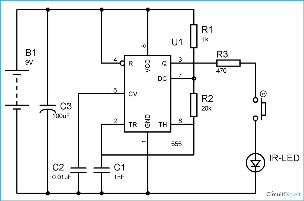
Understanding the Basics of an IR Receiver Wiring Diagram
An Infrared (IR) receiver wiring diagram can help you understand how a particular infrared receiver works. It offers a visual way to interpret the physical layout of an IR receiver. With this diagram, you can gain an understanding of the components and their respective functions. In addition to showing which parts work together, a receiver wiring diagram also helps reveal how high-end systems operate.
When used in conjunction with a user manual, a wiring diagram can provide insight into the inner workings of any infrared control system. By examining the wiring diagram closely, you can learn to construct basic circuits to better understand the components of an infrared device. Furthermore, it’s a great reference source for technicians to locate potential problems when troubleshooting.
What Are The Different Components In An IR Receiver Wiring Diagram?
An IR receiver wiring diagram is composed of several components. The most essential component is a type of sensor called a photodiode, which turns received light into electrical signals. This type of light is invisible to the human eye, making it ideal for control systems since you can’t be sure if somebody is using your remote or not. A voltage regulator converts the current back down to a usable level for operating the electronics, which are then connected to LED lights, transistors, microprocessors, and other devices.
How Does An IR Receiver Wiring Diagram Differ From Standard Wiring Diagrams?
Compared to standard wiring diagrams, IR receiver wiring diagrams are more complex. That’s because an IR receiver requires multiple components that must all be connected properly in order for the system to work correctly. In addition, the diagram must reflect the actual circuit layout, meaning that each component is positioned in the exact place where the wiring diagram specifies. Furthermore, the components must be correctly connected to the amplifier, signal mixer, and other components in order for the system to function.
Tips for Understanding IR Receiver Wiring Diagrams
Interpreting an IR receiver wiring diagram can be daunting at first. However, with patience and careful observation, you can decipher the diagram and interpret it correctly.
- Label each component: When you look at a wiring diagram, each component should have a descriptive label next to it. This will make it easier to identify each part and follow the wiring instructions.
- Note the terminal points: Since different components rely on different power sources, you need to note each component‟s terminal points to ensure they will be connected correctly.
- Logically connect the components: As you follow the wiring diagram, each connection should logically lead to the next. If something doesn‟t make sense, go over the wiring instructions again.
Conclusion
Understanding an IR receiver wiring diagram is actually simpler than it looks. Once you label the components and familiarize yourself with the electrical symbols, the wiring instructions become more straightforward. With patience and a methodical approach, interpreting wiring diagrams can be fun and rewarding in the end.

How To Build An Infrared Ir Phototransistor Receiver Circuit

Infrared Remote Control Transmitters Circuits Eleccircuit Com

Ir Remote And Receiver With Arduino Tutorial 4 Examples

Ir Remote Control Receiver Pinout Diagram 14core Com

Ir Sensor Circuit Diagram Types Working With Applications

Ir Remote Control Receiver Circuit Diagram

Ir Sensor Circuit Diagram Types Working With Applications

Automatic Fire Alram Circuit Using Transistor Ic And Ardino

How To Send And Receive Data Over Ir Signals With An Arduino

Improved Infrared Detector Circuit

Self Made Usb Infrared Receiver To Remote Control Your Pc Solder Instruction And Circuit Of The Ir

Tsop1738 Ir Receiver Pinout Working Arduino Examples Applications
Tsop1838 Ir Receiver Pinout Datasheet Features Equivalents

Ir Transmitter And Receiver Circuit Diagram

Wiring Trinket Gemma Ir Control Adafruit Learning System

Infrared Transmitter Receiver With 555 Under Repository Circuits 25389 Next Gr

Ir Transmitter And Receiver Circuit Diagram

Wiring The Infrared Receiver For Universal Remote Control 14core Com

Remote Control Switch Circuit Ir On Off

Infrared Sensor