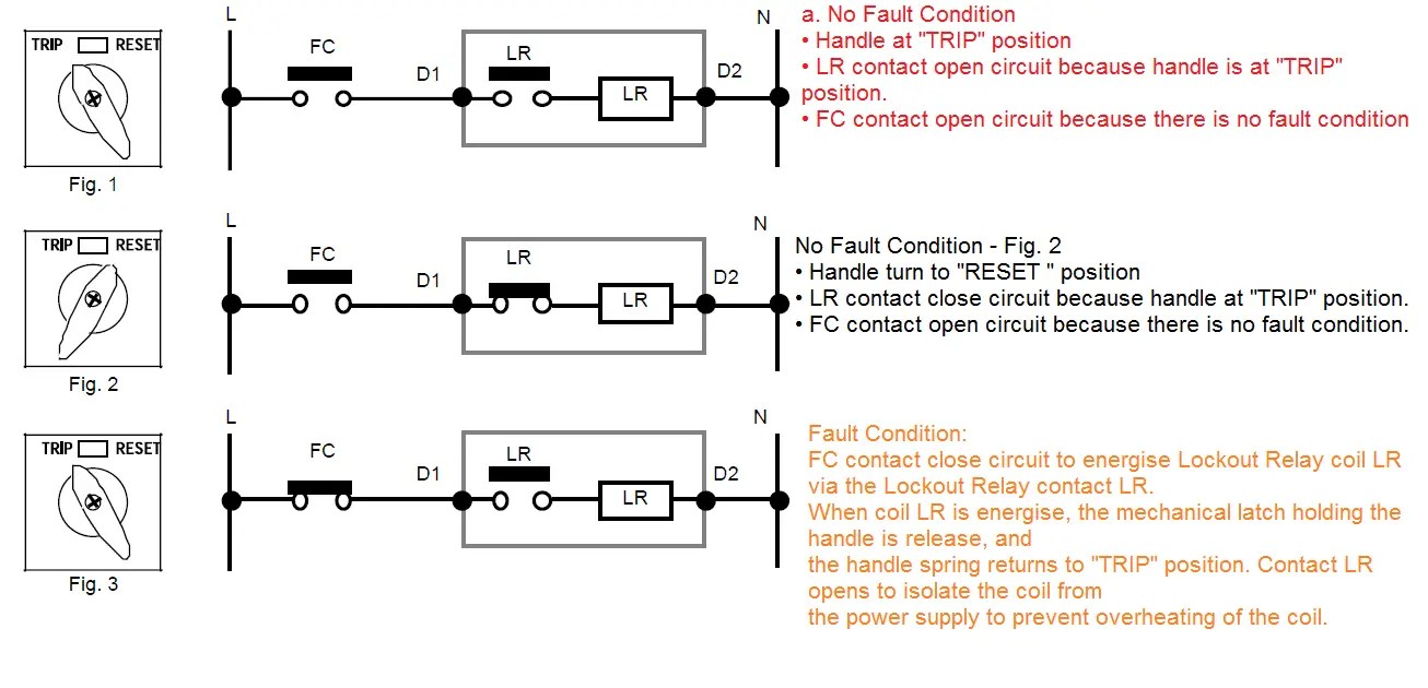
Understanding Lockout Relay Wiring Diagrams
Lockout relays are fundamental components of electrical equipment to protect people and machines from hazardous conditions. Understanding the importance of lockout relay wiring diagrams is essential for both small and large-scale installations. A tool that allows configuring instructions to a specific machine’s needs, lockout relay wiring diagrams provide an effective way to reduce potential risk when working with complex systems.
In this article, we will explore the types and uses of lockout relays, examine wiring diagrams, and look at how to implement lockout circuitry. By taking a deeper dive into these topics, you can maximize safety while minimizing costs by properly understanding wiring diagrams and the functions of lockout relays.
Types and Uses of Lockout Relays
Lockout relays are designed to shut off power quickly when there is a need to improve safety to personnel working on or near certain electrical devices. A lockout relay can be used to prevent accidental starts, and can also be used in systems where circuit energization can cause harm.
When integrated within various safety systems, lockout relay functions can include emergency stop controls, protective door interlock, fault detection, and process optimization. Their primary goal is to enhance security and reduce risk, but they can also allow operators to perform more efficiently as these devices can control multiple functions simultaneously.
Lockout Relay Wiring Diagrams
Lockout relays are typically consisting of a coil, contactor, and typical overload protection. The following basic wiring diagram illustrates this setup:

The most important aspect of any lockout wiring diagram is understanding the designations of each component in the system. The coil is the ‘heart’ of the relay and is generally labeled A in the diagram. It is normally powered through a 24-volt DC source such as a battery or power supply. The contactor is denoted by B in the wiring diagram and is the switch that allows current to pass from the coil to the load. This is where the risk of a hazardous situation can occur if the contactor is not notified that it needs to close.
How to Implement a Lockout Circuit
Implementing a lockout circuit requires an understanding of how the components interact with each other. In order to shut off the power when needed, the coil must be turned off first, followed by the contactor. Then, when the lockout signal is sent, the voltage will turn off, closing the contactor and shutting off the power to the circuit.
The necessary components for a lockout circuit include: the 24-volt DC power supply, the pulse generator, the control board, the alarm, and the relay control switch. The 24-volt power supply is used to power the coil and contactor, the pulse generator is used to send the signal to the control board, the control board is used to activate the lockout circuit, and the alarm is used to alert the operator of a lockout situation. Finally, the relay control switch should send an electrically isolated signal to the other components.
Once all of these components are connected correctly, the lockout circuit should be operational and ready to respond to a lockout signal. Before the lockout circuit can be put into use, it must be tested to ensure that the lockout signal is reliable and triggers the circuit correctly. Once these tests are done, regular maintenance should be done to make sure that the circuit remains safe and effective.
Conclusion
Understanding lockout relays and the importance of lockout relay wiring diagrams will help avoid hazardous situations and make operating electrical equipment much safer. If you know the different components and understand how they interact, you can use lockout circuit diagrams to keep people and machines away from electrical and mechanical dangers. By educating yourself and understanding how lockout relays work, you can feel confident and secure that your lockout system is working correctly.

Lock Out Relay Lor Series 26 Push To Test Shallco Inc

Icm Lockout Relay Icm220b Shortys Hvac Supplies

3 Phase Outdoor Electric Wiring With Lockout Relay Fully4world

Icm220 L P R Manualzz
M A Refrigeration Engineering Inicio Facebook

Lockout Relay Working Function 86 Electrical4u
The Misunderstood Lockout Relay Hvac School

Lock Out Relay Lor Series 26 Push To Test Shallco Inc

Control Relay What Is A

Methods Of Deceleration Plugging General Principles Electric Motor Control

Anti Pumping And Lockout Relays

Circuito Completo De Um Conversor Dc Scientific Diagram

Fault Code 474 Starter Solenoid Lockout Relay Justanswer

Functional Description For Tcs Relay 7pa30 Siemens Electrical Engineering
84 Heritage Starter Lockout Relay Logic Yamaha Xs650 Forum
How Does Lockout Relay Function Quora

Bf 3r Lockout Relay Arteche
