Understanding Plc Wiring Diagram Symbols: A Detailed Guide
Programmable Logic Controllers (PLCs) are the backbone of any automation system. From home automation to space exploration, PLCs are used to automate and control industrial machinery, processes, and safety systems. One of the most important components of PLCs are the wiring diagrams used to program them. Knowing how these diagrams work is essential for understanding and troubleshooting PLCs.
Wiring diagrams are the key to unlocking the mysteries of PLCs. These detailed drawings contain all the information needed to configure a PLC system and make it work. With their various symbols and lines, they can help both experienced engineers and novice users to get an idea of what needs to be done in order to create a successful PLC setup.
The Purpose of Plc Wiring Diagrams
The primary purpose of Plc wiring diagrams is to provide a comprehensive guide to configuring a PLC system. It helps the engineer identify what components are needed to be connected, what their connectivity should look like, and shows which specific connectors should be used for each type of wiring. Without the wiring diagram, it might be difficult to determine the exact configurations and logic that needs to be implemented during the installation process.
Usually, a Plc Wiring Diagrams will include a list of all the parts required to set up a PLC system. This gives the engineer an overall view of what needs to be incorporated into the setup as well as the precise cable lengths and connector types needed. In addition, they can be used to diagnose and troubleshoot existing installations, especially if the engineer is not very familiar with PLCs.
Plc Wiring Diagrams: Key Components
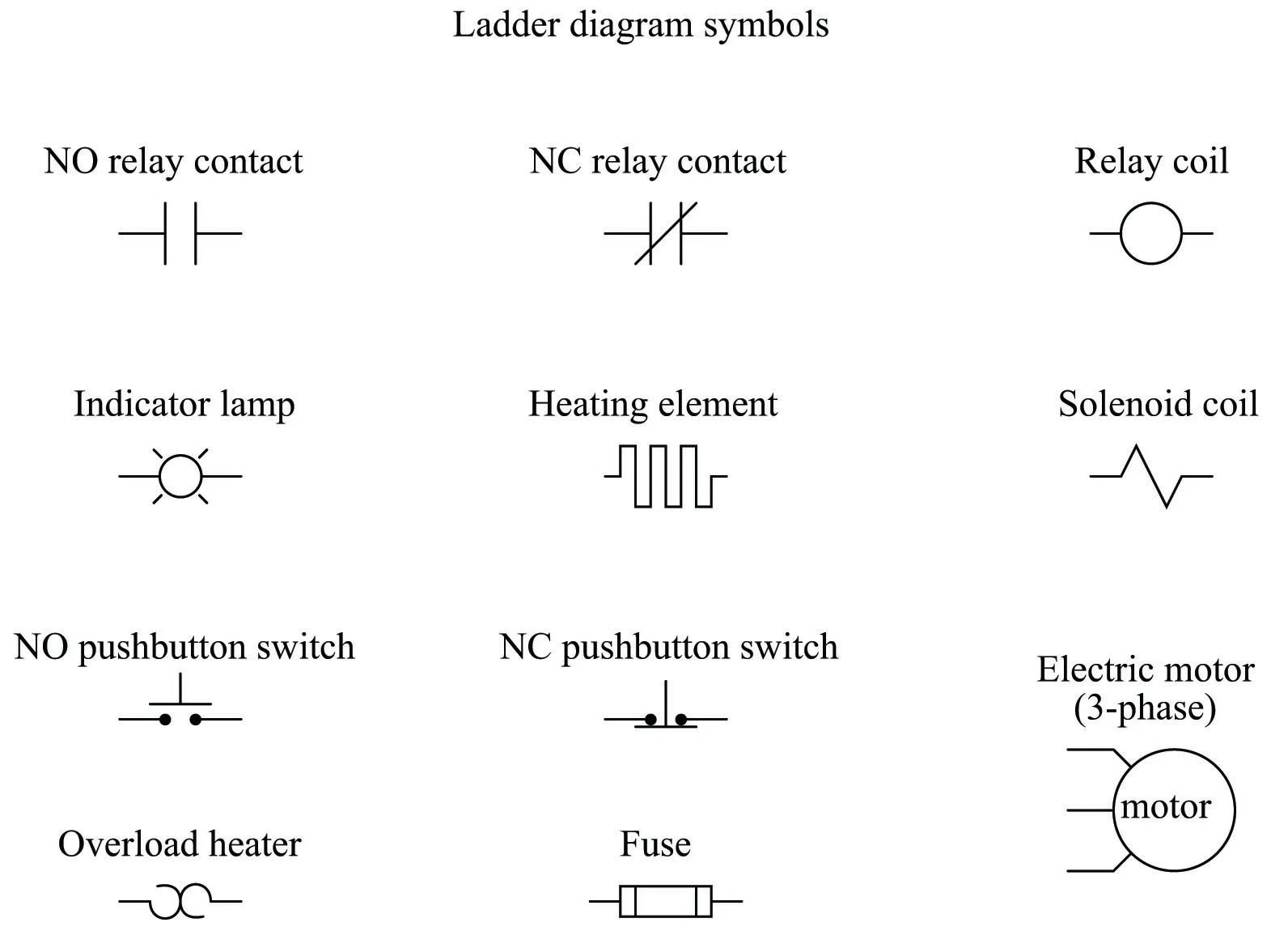
When it comes to wiring diagrams, understanding how to read the symbols is key to adequately setting up the system. There are several standard symbols used for PLC wiring diagrams, including inputs, outputs, power sources, and so on. Here’s an overview of what each symbol means:
- Power Source: This symbol usually represents the main power source of the system, such as any batteries or alternators.
- Connectors: These two-letter symbols indicate the type of connection used between parts. For example, ‘Mx’ denotes a male-to-female connection, while ‘Fx’ represents a female-to-female connection.
- Inputs: The larger circles on the diagrams are input signals from sensors or other PLC-connected devices.
- Outputs: Usually represented by squares, outputs are PLC-generated signals that may be sent to motors, actuators, and other devices.
- Modules: The black diamonds show the data links, connecting a PC to the PLC.
Conclusion
Although Plc Wiring Diagrams may seem complex at first, understanding and interpreting the various symbols is not as intimidating as it may seem. With careful study, even a novice user can gain the basic knowledge required to configure a PLC system.
Keep in mind that it is also possible to find tutorials and other helpful resources online. With a bit of practice, it won't be long before you're able to troubleshoot any existing system or complete a new one with ease using Plc Wiring Diagram Symbols PDF files.

Jic Standard Symbols For Electrical Ladder Diagrams Womack Machine Supply Company
Typical Electrical Drawing Symbols And Conventions

Motor Circuits And Control Applied Electricity

Programmable Logic Controllers Plc Ladder Electronics Textbook

Ladder Logic Symbols All Plc Diagram

Wiring Design Electrical Circuit Schematics Solid Edge

Using Ladder Logic For Gray Code Conversion Plcdev

Residential Wire Pro Software Draw Detailed Electrical Floor Plans

Relay Circuits And Ladder Diagrams Control Systems Automation Textbook

Electrical Panel Wiring Diagram

Electrical Panel Wiring Diagram

Plc Wiring Diagrams Digital Signals Techniques

Electrical Diagram Training Gray Furnaceman Furnace Troubleshoot And Repair

How To Read A Plc Wiring Diagram

Plc Programmable Logic Control Block Diagram Input Output Modules D E Notes

Electrical Panel Wiring Diagram

International Maforce 7 2010 Electrical Circuit Diagram

Wiring Diagrams Explained How To Read Upmation

Electrical Panel Wiring Diagram