Reversing the Single-Phase Induction Motor With A Wiring Diagram
The single-phase induction motor is a complex machine that has been successfully used in many applications for a long time. Despite its complexity, it is relatively simple to operate and maintain. The upcoming sections will discuss the different components and design of single-phase induction motors and how to reverse it in detail with a wiring diagram.
One of the advantages of using a single-phase induction motor is the ability to reverse its direction via reversing the current. However, this also entails understanding how the wiring diagram works when it comes to the polarity and rotation of the windings. Understanding the wiring diagrams of the single-phase induction motor enables one to solve any potential problems that may arise with the motor’s performance.
Understanding Standard Wiring Diagrams
It is common knowledge that most standard types of single-phase induction motor have three terminals – one for the neutral, one for the starting winding, and the other for the main winding. This forms the basic for the wiring diagram. The wiring diagram includes information on the physical arrangement of the components and how they are wired. These diagrams consist of three main elements: the starter, the main winding, and the neutral terminal. Additionally, the wiring diagram indicates the direction of the windings, as well as the connection and support points.
Reversing the Direction of the Motor
To reverse the direction of the single-phase induction motor, the current that is running through the windings must be reversed. To do this, the connections must be changed from the neutral side to the starting winding side, or vice versa. This can be done by using a switch or relay. By reversing the polarity of the current, the power source's current going into the motor starts running in the opposite direction, thus causing the motor to run in the opposite direction.
Implementing Reversal Wiring Diagram
Implementing a wiring diagram for the reversal of the single-phase induction motor requires an understanding of the circuit connections. First, the circuit should be laid out as it would be for normal operation. This makes it easier to understand the circuit. Once the circuit is laid out, the connections from the neutral terminals to the starting winding must be switched. This will change the direction of the current and the direction in which the motor rotates.
To make the process easier, a special switch should be used for the reversal of the single-phase induction motor. This switch is designed to control the direction of the current without having to change the connections manually or reset the breaker switch. Wiring diagrams should also be consulted to ensure that all the connections are functioning correctly.
Conclusion
It is essential to understand the wiring diagram for the single-phase induction motor to properly reverse its direction. The wiring diagram contains important information about the physical arrangement of the components and how they interact with each other. These diagrams can be used to perform maintenance and troubleshooting on the motor, as well as to control its direction of rotation. Reversing the single-phase induction motor typically involves reversing the connections from the neutral side to the starting winding side, or vice versa, to reverse the current direction.
By following these instructions, one can easily reverse the direction of the single-phase induction motor with a wiring diagram. This allows the user to make the necessary adjustments quickly and efficiently to ensure optimal performance from the motor.

3 Phase Forward Reverse Switch Wiring Diagram Earth Bondhon

Forward Reverse 3 Phase Motor Control Ecn Electrical Forums
Electrical Electronic Systems Forward Reverse 3 Phase Ac Motor Control Wiring Diagram Star Delta Main Circuit 1 Mcb Mini Circut Breaker 2 Fc

How To Wire 3 Phase Induction Motor Ato Com

Forward Reverse Direction Of Induction Motor And Dc Electrical4u

Single Phase Induction Motor Working Electrical Academia

Forward Reverse Direction Of Induction Motor And Dc Electrical4u

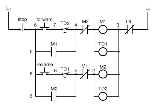
Motor Control Circuits Ladder Logic Electronics Textbook
Wiring A Single Phase Motor Forward Reverse Electronics Forum Circuits Projecticrocontrollers
.png?strip=all)
Acp M Ac Induction Motors

Transformers Phase Converters And Vfd Is There A Way To Reverse My Motor With This Drum Switch Practical Machinist Largest Manufacturing Technology Forum On The Web

How To Use Three Phase Motor In Single Power Supply Electrical Engineering Centre

How To Wire Single Phase Motor Ato Com
How To Wire A 6 Pin On Off Toggle Switch 110 Volt Ac Motor For Reverse And Forward With Four Wires From The Simple Explanation Quora

Reverse Motor Starters

How To Use Vfd For Single Phase Motor Ato Com

Motor Control Circuits Ladder Logic Electronics Textbook

Split Phase Motors

Star Delta Starter Working Circuit Advantages Disadvantages
