Breaking Down the Basics of a T1 Circuit Wiring Diagram
When it comes to electronic machines, wiring diagrams are critical for understanding how all of the different parts work together. The T1 Circuit Wiring Diagram is no exception, and learning the ins and outs of the diagram can help technicians and engineers better diagnose and repair machines and equipment within their organization.
A T1 Circuit Wiring Diagram provides a detailed flowchart of a circuit's wiring below a certain point within an electrical system. The diagram is essential for connecting and testing a wide variety of electrical devices. With the diagram, technicians or service professionals can easily identify any discrepancies that may arise with the wiring. Thus, being equipped with the basics of a T1 Circuit Wiring Diagram is not only helpful but also necessary for many technicians or engineers.
Know the Components of a T1 Circuit Wiring Diagram
A T1 Circuit Wiring Diagram would typically include several components such as a power input connector, transformer, fuses, resistor, and even larger components including chips, circuit boards,an LED display, etc. A diagram of an entire circuit, such as the T1 Circuit Wiring Diagram, would generally include all of these components and also specify which wires are connected to each component. Understanding the purpose of each component of the T1 Circuit Wiring Diagram is key to understanding the diagram more easily.
Be Familiar with Labeling Conventions
Labeling conventions within the T1 Circuit Wiring Diagram is another important aspect to be aware of in order to accurately read the diagram. Certain components will be labeled with various letters and symbols depending on their function. Knowing these conventions is essential to being able to understand the diagram quickly and correctly. Typically, components within a T1 Circuit Wiring Diagram will be labeled with letters, numbers, or a combination of both. Being familiar with these conventions can help an engineer or technician read the diagram more effectively.
Test and Troubleshoot
In the event a problem arises with the wiring, it is beneficial to know how to troubleshoot the issue. Depending on the complexity of the circuit, it may be necessary to test multiple components of the T1 Circuit Wiring Diagram before determining the root cause of the problem. It is essential to verify the integrity of the wiring by checking the connections against the diagram. Inability to do so can lead to further complications and cause more issues. Understanding the fundamentals of a T1 Circuit Wiring Diagram gives engineers and technicians the necessary tools in order to quickly identify an issue and resolve the problem.
Overall, learning the basics of a T1 Circuit Wiring Diagram is essential for all engineers and technicians. Being aware of the various components of the circuit and labeling conventions will enable technicians and engineers to diagnose and repair the wiring more accurately. Testing and troubleshooting methods are also vital for quick resolution of problems. Ultimately, having an understanding of this wiring diagram helps to ensure that the circuits are functioning properly at all times.

How To Wire A 3 Way Switch Wiring Diagram Dengarden

How To Read Car Wiring Diagrams Short Beginners Version Rustyautos Com

T1 Cable Rj48c And Rj48s Rj48x 8 Position Jack Pin Out For Termination By Bell

Ceiling Fan Wiring Diagram Power Into Light

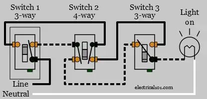
4 Way Switches Electrical 101

Micro Usb C Wiring Diagram Detail Connection Sm Tech

3 Way Switch Wiring Diagram

Schematic Wiring Diagram Of The Much Simplified Cerebellar Circuit Scientific

Master Switch Wiring Diagram

Plc Training Reading Electrical Wiring Diagrams And Understanding Schematic Symbols Tw Controls

Float Switch Installation Wiring Control Diagrams Apg

4 Way Switch Wiring Electrical 101

Resources

Light Switch Wiring Diagram Multiple Lights

Learn What Is Inside A Modern Ats Panel And How To Analyze The Circuit Diagrams Eep

Three Way Switch Wiring How To Wire 3 Switches Hometips

How To Wire A Switch Box Electrical Board Connection

Developing A Wiring Diagram Circuit 2

How To Wire A Light Switch Simple 3 Way 4 Wiring

Schematics And Wiring Diagrams Circuit 1