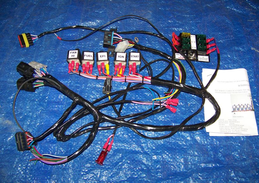
Understanding the Power of a VR V8 Auto Wiring Diagram
For car owners and mechanics alike, auto wiring diagrams have long been essential for repairing and upgrading vehicles. Of all the available diagrams, one of the most powerful is the VR V8 Auto Wiring Diagram. It offers insight into the electrical connectivity and warnings about potential problems that could cause safety issues while driving. This diagram packs valuable information in an easy to understand format, allowing for quick diagnosis and repair of a wide range of cars.
No matter the make or model of your vehicle, understanding the power of a VR V8 Auto Wiring Diagram is essential for identifying common automotive electrical issues that could endanger you and your passengers. Here’s what you need to know before you start tinkering around under the hood.
What Does the VR V8 Auto Wiring Diagram Include?
At first glance, a VR V8 Auto Wiring Diagram may look complex and daunting. However, it is designed to be easy to understand and provide straightforward, accurate information that applies to all models of a manufactured car. The diagrams offer a simplified representation of an automobile's electrical system and reveal the structure of the wires and connections between multiple components.
The VR V8 includes electrical symbols for easy identification and labeling of the components. Each symbol is standard and has its own color-code, allowing for comprehensive understanding without confusion. Furthermore, it shows ground points at the bottom of the diagram to ensure that the system has a safe and secure connection of components to the ground point.
Simplifying Troubleshooting With a VR V8 Wiring Diagram
For mechanics and non-mechanics, one of the benefits of using VR V8 wiring diagrams is that they make troubleshooting electrical problems straight-forward. Even complex issues such as short circuit malfunctions can be quickly diagnosed by examining the diagram. It's important to look at circuitprotection elements if the wiring diagram indicates a circuit protection device should be present. The diagram will also show optional connectors, wire colors and pin numbers, which enable the engineer or technician to trace connections more easily.
Information about auxiliary lighting circuits, airbag systems, anti-lock brakes and air conditioning modules can also be found in a VR V8 wiring diagram. The comprehensive nature of the diagrams provides a huge advantage because it permits anyone to identify and self-diagnose problems even when they are not familiar with automotive engineering.
What Are The Benefits of Using a VR V8 Wiring Diagram?
Using a VR V8 Auto Wiring Diagram helps save time since technicians can quickly pinpoint the location of any fault in an electrical system, as well as diagnose the problem. Because they feature precise details about ground points and other specialty ports, they are also used to increase safety when making repairs and upgrades.
The ability to diagnose unusual electrical problems that can cause intermittent malfunctions or even sudden failures is invaluable in saving time and money. Having a clear idea of what is required for proper maintenance and repairs means that car owners can properly address any underlying issues before the small issue gets bigger and more expensive to tackle.
In conclusion, the VR V8 Auto Wiring Diagram provides an accurate, up-to-date source of information for resolving electrical problems quickly and safely. By arming yourself with this powerful tool, you’ll be able to keep your vehicle running smoothly and stay safe on the road.

Volkswagen Touareg Pdf Work And Repair Manuals Wiring Diagrams

V3 Main Board
Ms1 Extra Ignition Hardware Manual

Micromachines Free Full Text A Direct Writing Approach For Fabrication Of Cnt Paper Based Piezoresistive Pressure Sensors Airflow Sensing Html

Ms1 Extra Ignition Hardware Manual

Holden Vn Commodore V8 Electronic Control Module Wiring Diagram 8jlk87m220l5

Isuzu Npr W4 4000 V8 Efi Gasoline Engine Truck Forward Tiltmaster Service Manual By Heys Issuu

Edis Megajolt Ignition Support Thread Page 25 The E Type Forum

Holden 304 Has New Ignition Module Plugs Leads Coil Dizzy Power To No Problem Checked And Rechecked Plug

2 3 Wire Crank Sensor Wiring Diagram With Pictures

Ms1 Extra Ignition Hardware Manual

Wright Stander Wiring Diagram Deals 50 Off Www Ingeniovirtual Com

Ignition Module Wiring The V8 Owners Forum

1994 Holden Commodore Photos Informations Articles Bestcarmag Com

Wiring Kits V6conversions

Holden Commodore Haynes Repair Manuals Guides

Work Auto Manuals Fault Codes Dtc Wiring Diagrams Free Workautomanuals

Holden Car Pdf Manual Wiring Diagram Fault Codes Dtc