The Basics Of Western Sander Wiring Diagrams
When it comes to electrical and wiring work, wiring diagrams are an essential tool. Not only do wiring diagrams provide a holistic overview of all the various elements of the wiring system, but they can also provide invaluable assistance when troubleshooting or making repairs. For those unfamiliar, a wiring diagram is simply a blueprint of the electrical system, outlining the necessary components and their connections.
Nowhere is this more apparent than in the realm of lap gilders and sanders—like the commonly used Western sander. A Western sander wiring diagram allows us to map out the important points in the wiring system used by these tools, enabling us to ensure that everything is hooked up properly and functioning as intended.
Safety Considerations
Before engaging in any sort of electrical work, both the amateur and professional should become familiar with safety standards as set forth by the National Electric Code. Additionally, all electrical and wiring components must meet UL and/or CSA safety requirements. Furthermore, the individual working on the wiring should be qualified, familiar with and able to use appropriate tools, and take the necessary safety precautions.
Components Of Western Sander Wiring Diagrams
Western sanders require split wiring with separate power source and motor wires. Additionally, a 3-prong grounded outlet must be installed. The circuit breaker must be rated as 20-amp, 120-volt and designed for a continuous load. Further, the positive wire needs to be marked with green insulation tape. Other essential parts include:
- Motor capacitor
- Power switch
- Emergency shut-off
- Rocker switch (on/off)
- Speed control (optional)
Mapping Out The Wire Connections
Once the essential components have been secured, it's time to map out the wire connections of the Western sander wiring diagram. Motor wires should always leave from the particularly side while power source wires can travel from either side. The power switch should be placed near the wall while the emergency shut-off should be accessible while operating the device. The speed control should always link directly to the power switch.
Testing And Troubleshooting
Once all the wires are connected according to the wiring diagram, the next step is to test the sander and see if its functioning correctly. This is best done by carefully plugging it into an appropriate outlet and turning it on. In case of any malfunctioning, standard troubleshooting techniques—as outlined in the user's manual—can be followed in order to resolve it.
By following a clear and easy-to-understand Western sander wiring diagram, users can confidently tackle the relatively simple task of wiring together these specialized electric machines. With the right tools and safety precautions, everyone can create a safe and functioning electric sander.

Tornado 1 5 8 2 Cu Yd Serial 090527 120430 Hopper Spreader V Box Salt Diagrams Parts With Western Poly Drive Components Snowplow Warehouse

Western Ice Breaker Hopper Spreader Drive Components Parts

Western 1000 Spreader Control Parts Snowplowsplus

Qte Western Parts Snow Plow And Spreader

Western Wiring Unimount Chevy 61716

Western Striker Series Mechanic S Manual Pdf Manualslib

Lt Spreaders Wiring Diagram Service Manual Library

Correlation Coefficients Of Diffusion Controlled Kinetics Models At Scientific Diagram

Wiring Harness Diagram For Power V Rt3 Parts Iteparts Com
Chapter 1b Electrical Schematics Rev 3 1 170313 Des

Western Low Profile Model 500 Tailgate Spreader

Western Salt Spreaders Westernparts Com

Western Pro Flo Owner S Manual Manualzz

Poly Caster Fleet Flex Cables Harnessing Fisher Parts List

69906 Western Striker Salt Spreader Wiring Harness

Air And Electrical Systems Western Star Trucks

Western Ice Breaker Hopper Spreader Drive Components Parts

Western Mvp Snowplow Hydraulics Hose And Ings Parts

Western Plow Parts Starting With P Snowplowsplus

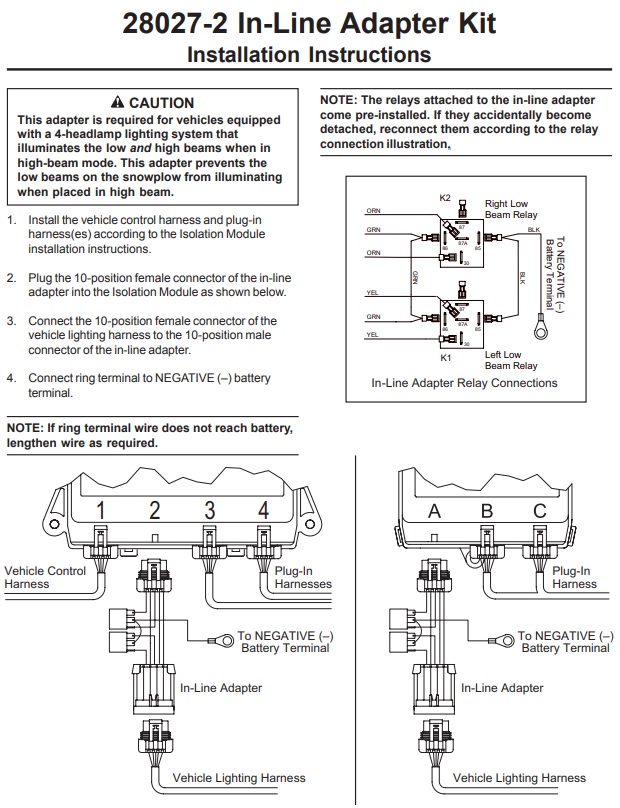
28027 3 Inline Low Beam Disable Module Adapter