Understanding Wiring Diagram Capacitor Symbol & Its Significance
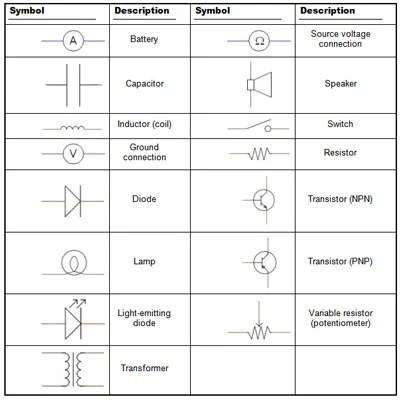
In electronics, wiring diagram capacitor symbol refers to the symbols used in a schematic circuit or wiring diagram. This refers to a network of interconnected devices or components that can be used to generate a desired electrical current or voltage. It is a schematic representation of the connections and connections between the various components of the circuit, as well as the overall operation of the system.
A capacitor is a component within an electronic device which stores electrical charge. The capacitor symbol is an important part of wiring diagrams and it tells technicians how the capacitor is connected to other components, as well as its function within the circuit. It is essential for technicians to understand this symbol in order to properly understand how to properly build and troubleshoot circuits.
What Does a Wiring Diagram Capacitor Symbol Represent?
The wiring diagram capacitor symbol represents the connection between two components, namely the capacitor and another component within the electronic circuit. This symbol is usually represented by an arrow pointing to a line made up of parallel lines, with the arrow head representing the capacitor. The arrow represents the flow of electricity from the capacitor to the other component.
Significance of Using Wiring Diagrams
Wiring diagrams play an important role in understanding circuitry and its components. A wiring diagram helps technicians in understanding the arrangement of components when designing or troubleshooting a particular circuit. It allows technicians to understand which components are connected to which wires and then how these components interact with each other.
Having a proper and clear wiring diagram is essential since it can help identify any potential problems or issues with the circuit. It will provide important information about how the components interact with each other, helping technicians to work out likely solutions and preventing further damage to the system.
Other Aspects of Wiring Diagrams to Consider
In addition to capacitor symbols, there may also be a few more components to consider when making wiring diagrams. For example, the schematic will generally include resistors, transistors, diodes, and capacitors, among other components. These components are all important to the circuit, but their placement and form might still differ depending on the application.
Also, when making a wiring diagram, it’s important to also consider voltage drop across each component as it works with other nearby components. The resistance associated with each part must also be considered because it affects the overall resistance of the entire circuit, including the effects of bias currents.
Key Considerations With Wiring Diagrams
When creating a wiring diagram and using the capacitor symbol, there are a few key considerations. For example, it is important to note the connection type of the capacitor, such as whether it is connected in series or in parallel. A technician must also be aware of the capacitors process of connecting with other components, such as whether it works with single-ended or dual-ended connections.
In addition, electroluminescent (EL) products, which are used to create light with certain materials, have electrically isolated power supplies. As such, EL products are particularly sensitive to external electrical discharge, which is why it is essential to use special attention to wiring diagrams when installing these components.
Conclusion
The wiring diagram capacitor symbol is a very important part of any schematic diagram, as it indicates the connection between components, as well as the overall operation of the circuit. By understanding this symbol and its significance, technicians can properly troubleshoot and build electrical systems without fear of introducing further damage. Along with this symbol, technicians should also consider a few other aspects of wiring diagrams, such as the placement of components, voltage drops, and resistance associated with each part.

Electrical And Electronic Symbols Electrical4u

Electrical Symbols Lamps Acoustics Readouts Design Elements Measuring Instruments Vector Stencils Library Siren Circuit Symbol

Circuit Diagram Of Single Phase Capacitor Start Induction Motor With Scientific

Jic Wiring Symbols Plc Engineers Community

Appendix C Circuit Schematic Symbols Applied Electricity

Electronics Schematics Commonly Symbols And Labels Article Dummies

What Is The Meaning Of Schematic Diagram Sierra Circuits
What Are The Electronics Symbols Quora

Schematic Symbols The Essential You Should Know

Electronic Symbol Capacitor Capacitance Png 800x379px Circuit Diagram Decoupling Free

Electrical Schematic Symbol Capacitor Free Cad Block And Drawing

How To Draw Schematic Symbols Simply And Easily 2 Printed Circuit Board Manufacturing Pcb Assembly Rayming

Variable Capacitor Electronic Symbol Electrical Network Wiring Diagram Changeable Angle Electronics Rectangle Png Pngwing

Standardized Wiring Diagram Symbols Color Codes August 1956 Por Electronics Rf Cafe

Capacitor Start Run Motors

Capacitor Schematic Symbols

Wiring Diagram Everything You Need To Know About

Appendix C Circuit Schematic Symbols Applied Electricity

Tuning Capacitor