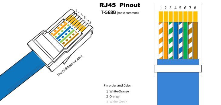
Understanding Wiring Diagram For Rj45 To Rj11
In order to understand how an RJ45 to RJ11 wiring diagram works, it is important to have a basic understanding of the two different types of cabling that is used in communications networks. Both RJ45 and RJ11 are used in applications such as voice over IP (VoIP) and computers, but for different reasons. It is also important to know the different types of connectors and wiring diagrams that can be used when setting up a network.
An RJ45 connector is often used in long distance networks as it supports a higher cable capacity and is physically larger than the RJ11 connector. This type of wiring diagram typically uses 8 conductors coupled together using 4 pairs of twisted cables. By using 8 conductors, it can support higher data rates over longer distances than a similar RJ11 connector.
Understanding the Different Types of Wiring Diagrams
A wiring diagram is a simplified representation of how electrical devices are connected in a system. It is composed of different components such as control points and wire colors that give information on how the circuit should be wired. It is not possible to draw a wiring diagram without planning what components need to be used and where they will be positioned in the system.
There are three types of wiring diagrams that are usually found in systems: star, cross and closed circuit. In a star system, each device is connected to a single star point or power source. This type of diagram is often used in small office environments. In a cross wiring diagram, each device has two electrical connections, one to the power source, and one to another device. This type of wiring diagram is found in larger office buildings.
RJ45 to RJ11 Wiring Diagrams
When installing an RJ45 to RJ11 wiring diagram, it is important to remember that the power source is not connected to the line. The line must be connected to the two connectors that are needed in order to create a connection between the two networks. A diagram will often show the layout of the cables but may not provide detailed instructions on how to connect the cables.
It is important to note that there is no single standard wiring diagram for all applications. Instead, each application will require its own specific wiring diagram. This means that it is important to read through a manufacturer’s instructions carefully before starting to install the wiring for an application. It is also important to double check the connections once everything has been completed.
Advantages of Using Wiring Diagrams
The use of wiring diagrams can make installation of the communication network much easier and faster, reducing the risk of errors. They provide clear instructions on how to connect the cables and what orientation they should be in, making it easier to troubleshoot any problems that may arise during installation. Many manufacturers also provide detailed diagrams to help customers install the system correctly, saving time and money.
An RJ45 to RJ11 wiring diagram also allows you to easily identify any faults in the system before they become major issues. This can enable you to save time, money and stress. Additionally, they enable you to integrate new technologies and software quickly and efficiently, ensuring that a network is kept up-to-date.

Dobstuff Sky Commander Cable

Rj45 Pinout Showmecables Com

Doent For Technical Training Ppt

Ethernet Cable Wiring Diagram With Color Code For Cat5 Cat6 Etechnog
Telephone Line Rj25 Rj14 And Rj11 Pinout Diagram Color Codes Etechnog

Understanding Modular Connectors Faqs Engineering And Component Solution Forum Techforum Digi Key

Rj45 Vs Rj11 What Is The Difference Between And

Twitter 上的wiring Diagram What Is Rj45 Ethernet Cable Utp Wiring Https T Co Olb1envwbo Gz7iqpdntz

Rj 11 Pinout Wiring Diagram Registered Jack Category 5 Cable Work Angle White Png Pngegg
![]()
Appendix B Connector Pin Assignments

1 Port G Shdsl Mini Physical Interface Module Cable Specifications Technical Doentation Support Juniper Networks
Assembling The Shielded Rj45 Connector And Ethernet Cable Netengine Ar Hardware Installation Maintenance Guide Huawei

Yost Serial Device Wiring Rs232 On Rj45 Lammert Bies

China Rj45 Rj11 Rj12 Rj9 Telephone Patch Cord Cat3 Cable Indoor And Wire Cables 4core
Telephone Line Rj25 Rj14 And Rj11 Pinout Diagram Color Codes Etechnog

Rj 11 Category 5 Cable Rs 232 Wiring Diagram Pinout Weight Scale Angle Electrical Wires Engineering Png Pngwing

Easy Rj45 Wiring With Pinout Diagram Steps And Thetechmentor Com

Rj11 To Rj45 Cables


