Understanding Wiring Diagrams Contactors Motors – A Comprehensive Guide
Electrical wiring diagrams contactors motors are the heart of a majority of industrial machinery, from large manufacturing facilities to small businesses. Without properly wiring electrical systems, the efficient operation of a business or other organization is impossible. There are several different types of wiring drawings and diagrams we are going to discuss further in this article.
As machines become increasingly complex, there’s been more of a need for wiring diagrams contactors motors in order to properly configure and control them. However, understanding wiring diagrams contactors motors often seems like a challenge for those unfamiliar with the language and symbols used. This article will help readers better understand the basics of electrical wiring diagrams and their importance.
What Is A Wiring Diagram?
A wiring diagram is a simplified representation of an electrical circuit, showing its function, components, and connections in a clear, concise format. Wiring diagrams are particularly helpful when it comes to troubleshooting problems as well as replacing components. In addition, understanding the wiring diagrams contactors motors allows an individual to determine which nodes and circuits are controlled by each switch or device. The diagrams come in several forms including hand-drawn sketches, computer-generated visuals, text boxes, detailed schematics and even animations. Wiring diagrams are usually organized numerically and in order of the components in the system.
What Are The Benefits Of Knowing How To Interpret Wiring Diagrams?
If you’ve ever tried to replace a light fixture without consulting a wiring diagram or had to solder a difficult connection without correctly being able to interpret a wiring diagram, you’ve probably experienced the frustrations of guess work gone wrong. Electrical wiring diagrams give workers the ability to diagnose possible causes of power outages, shorts, and other potential safety issues. Preventing potential damage is essential as a code violation could prove costly in fines or repairs.
Furthermore, the ability to fluently read wiring diagrams contactors motors is essential if you plan on designing a new circuit. If you incorrectly wire a machine, it can cause extensive damage and unexpected downtime. Even if your cross-connections are correct, you won't have the graphic representation of parts and components to show or confirm any inconsistencies.
What Are The Basics Of Reading Wiring Diagrams?
The most important thing to remember while reading a wiring diagram is that it will always match the system it is describing. When looking at a wiring diagram, it should be easy to identify what each symbol or line is referencing. Furthermore, outlines representing components will match the outlines that are referenced within the diagram. Additionally, it’s important to understand the conventions used for numbering wires and outlining the layout, as they may have different conventions depending on the country, region, or procedure.
In addition, it is important to pay close attention to how current and voltage flow throughout the diagram. Many diagrams include lines that evoke arrows which suggest the direction of current flow. It is generally preferred for electricity to flow from the top down inside a wiring diagram, however this isn’t always the case. Wiring diagrams will also contain circuit protection devices such as fuses, breakers, and circuit interrupt switches, which all need to work together in order to provide a safe and reliable system.
What Types Of Wiring Diagrams Exist?
There are many different types of wiring diagrams contactors motors. Here we have listed many of the most common types of wiring diagrams used in industry:
- Raceway Layouts: These wiring diagrams illustrate the physical layout of the building using detailed views of the physical location of components (supply sources, fixtures, outlets, junction boxes).
- Electrical Service Entrance Diagram: This diagram will show you the major components installed in the building, such as the electrical meter, supply panels, transformers, service lines, and the termi/breaker box.
- Schematic Diagram: This wiring diagram will show the connections between multiple pieces of equipment and the routing of conductors in the enclosure or conduit.
- Wiring Detailed Diagram: A wiring detailed diagram will provide detailed information about a system. This may include detailed wiring diagrams for alarm, security, and HVAC systems – noting all connections, switches, relays, and loads.
- Interconnection Diagrams: This type of diagram will show the interconnections that are required for a specified system. This may include control system loops, logic diagrams, power interconnects, etc.
Conclusion
Understanding wiring diagrams contactors motors is a fundamental skill required for any electrical engineer or technician. Being able to interpret them correctly gives the technician the ability to troubleshoot and repair electrical problems, saving time and money. In addition, it ensures the integrity of the system, as well as making sure that safe procedures are followed.

Typical Ac Contactor Connection Diagram Using Start Stop Pushons Scientific

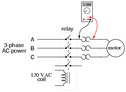
Contactors Electromechanical Relays Electronics Textbook
A Sketch Of The Electromagnetic Contactor B Magnetic Scientific Diagram

Motor Circuits And Control Applied Electricity

Start Stop Circuit What They Are Where And How To Wire
What Are The Functions Of Km1 And Km3 In Ats48 Soft Starter On Wiring Diagram Schneider Electric Thailand

Type Of Contactor For Direction Change Single Phase Im Electrical Engineering General Discussion Eng Tips

Contactorotor Starters

Pdf Schneider Electric Wiring Diagram Book Engineer Bilal Nasir Academia Edu

Contactorotor Starters

Contactors And Relays Construction Operation

The Principle Of Contactor Controlling Motor Forward Reverse Circuit

Star Delta Wiring Diagram Ideas For Android

What Is A Contactor

Contactor Construction Working Principle Types And Differences

Contactorotor Starters

Motor Control Circuit Wiring Inst Tools

The Difference Between Contactorotor Starters And Reduced Voltage

Overload Relay Definition Types And Principle Wira Electrical